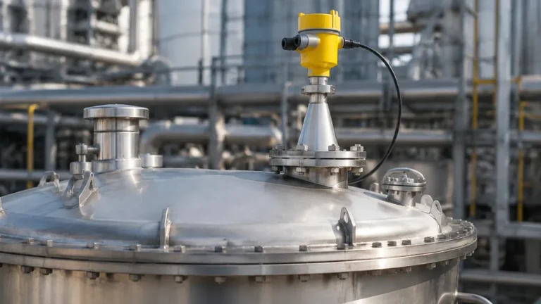
5408 Radar Level Transmitter
5408 Radar Level Transmitter: Engineering Principles and Application Guide
In modern process automation, the transition from contact-based measurement to non-contact technologies has significantly reduced maintenance overhead and improved system reliability. The 5408 radar level transmitter stands as a benchmark in this transition, utilizing Frequency Modulated Continuous Wave (FMCW) technology to provide high-precision level data in challenging industrial environments. This guide explores the technical foundations, selection criteria, and installation requirements for engineers and procurement specialists integrating these instruments into their facilities.
Understanding the Measurement Principle: FMCW Technology
Before selecting a Radar Level Meters solution, it is essential to understand the underlying physics that differentiate modern transmitters from older pulse-based systems.
The 5408 radar level transmitter operates on the Frequency Modulated Continuous Wave (FMCW) principle. Unlike traditional pulse radar, which measures the time-of-flight of a single microwave pulse, FMCW transmitters emit a continuous signal with a constantly changing frequency (a frequency sweep or "chirp").
1. Signal Emission: The transmitter sends a continuous microwave signal toward the product surface.
2. Reflection: The signal reflects off the surface of the media (liquid or solid) and returns to the antenna.
3. Frequency Comparison: Because the transmitter is constantly changing its emission frequency, there is a measurable difference between the frequency currently being transmitted and the frequency of the reflected signal that has just returned.
4. Distance Calculation: This frequency difference (the "beat frequency") is directly proportional to the distance the signal traveled.
FMCW technology offers a significantly higher signal-to-noise ratio compared to pulse radar. This allows the 5408 radar level transmitter to track the surface accurately even when the signal is weakened by foam, vapor, or turbulence, making it a preferred choice for critical process vessels.
Technical Selection Criteria
Choosing the correct configuration for a radar transmitter requires a detailed analysis of the process media and the vessel geometry. The following factors are decisive in ensuring long-term measurement stability.
Dielectric Constant (DK)
The dielectric constant of the media determines how much of the radar signal is reflected back to the sensor. High-DK materials like water (DK ≈ 80) reflect signals strongly. Low-DK materials like hydrocarbons (DK < 2.0) allow much of the signal to pass through, resulting in a weaker reflection. The 5408 series is engineered with high sensitivity to detect levels in fluids with DK values as low as 1.2, provided the correct antenna and installation parameters are met.
Process Conditions
Temperature and pressure fluctuations can affect the mechanical integrity of the transmitter. Standard industrial radar units typically handle temperatures from -60°C to +250°C. For high-pressure applications, the seal material (e.g., PTFE, PEEK, or Kalrez) must be compatible with the chemical composition of the process media.
Selection Table for Radar Level Transmitters
| Feature | Specification Detail | Application Suitability |
| :— | :— | :— |
| Technology | 2-Wire FMCW | High-accuracy liquid/solid level |
| Frequency | ~24-26 GHz / 80 GHz | General purpose to narrow beam requirements |
| Measurement Range | Up to 40m (standard) | Large storage tanks and process vessels |
| Accuracy | ±1 mm to ±3 mm | Custody transfer or precise process control |
| Operating Temp | -60°C to +250°C | Cryogenic to high-heat reactors |
| Pressure Range | Vacuum to 100 bar | Pressurized storage and vacuum distillation |
Installation Considerations and Constraints
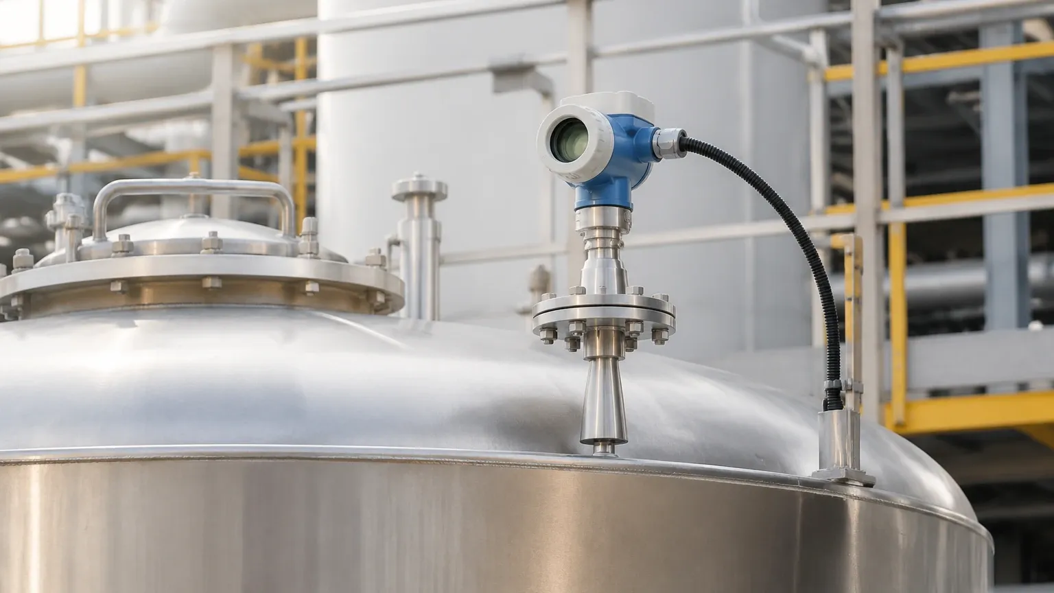
Correct physical placement is the most critical factor in the performance of a 5408 radar level transmitter. Even the most advanced FMCW signal processing cannot compensate for a fundamentally poor installation.
Nozzle Design and Placement
The transmitter should be mounted away from the tank wall to prevent interference from side-wall reflections. A general rule is to maintain a distance of at least 1/6th of the tank diameter from the wall.
* Nozzle Height: The nozzle should be as short as possible. If the nozzle is too long, it can create internal reflections that mask the true level of the product, particularly when the tank is nearly full.
* Internal Obstructions: Avoid mounting the transmitter directly above agitators, heating coils, or ladders. While software-based "false echo suppression" can ignore these static objects, they still reduce the total energy available for measuring the actual surface.
Beam Angle and Obstacles
Radar signals spread out in a cone. The beam angle depends on the antenna type and the frequency. A larger antenna or a higher frequency (such as 80 GHz) results in a narrower beam, which is ideal for avoiding internal obstructions in narrow vessels. For the 5408 radar level transmitter, engineers should calculate the beam diameter at the bottom of the tank to ensure it does not intersect with the vessel walls or discharge cones.
Metric Installation Clearances (Example)
* Minimum Distance from Wall: 200 mm to 500 mm (depending on tank size).
* Nozzle Diameter: Typically 50 mm (2") or 80 mm (3") to match antenna size.
* Dead Zone (Blocking Distance): Usually 0 to 300 mm from the antenna tip, where measurement is not possible.
Limitations and Application Risks
While the 5408 radar level transmitter is highly versatile, certain process conditions present significant challenges:
1. Heavy Foam: Extremely thick, dense foam (like shaving cream) can absorb the radar signal entirely, preventing any reflection from reaching the liquid surface. In such cases, a Guided Wave Radar (GWR) or a lower frequency radar may be required.
2. Heavy Agitation: Rapidly moving surfaces or vortices can scatter the radar signal. While FMCW technology handles this better than pulse radar, high-speed agitation may require the use of a stilling well to provide a calm surface for measurement.
3. Condensation and Buildup: While many antennas are designed with PTFE drip-off shields, heavy coating or crystallization on the antenna face will eventually attenuate the signal, requiring periodic cleaning or the use of an air purge system.
Maintenance and Diagnostics
One of the primary advantages of the 5408 series is the inclusion of advanced diagnostics. Modern transmitters provide a "Signal Quality" metric, which monitors the strength of the surface reflection relative to the noise floor.
* Preventative Maintenance: By monitoring signal quality, maintenance teams can predict when an antenna is becoming coated with residue before the measurement fails completely.
* Verification: Many units now support "Smart Meter Verification," allowing the electronics to be tested for accuracy without removing the device from the process or changing the level in the tank.
Frequently Asked Questions (FAQ)
Q: Can the 5408 radar level transmitter measure solids?
A: Yes, FMCW radar is effective for solids like plastic pellets, grains, or powders. However, the angle of repose of the solid material must be considered, as the signal may reflect away from the antenna if the surface is steeply sloped.
Q: Does the vapor space composition affect accuracy?
A: Unlike ultrasonic sensors, which are affected by changes in gas density and temperature, radar signals travel at the speed of light. Changes in the vapor space (e.g., nitrogen blanketing or steam) have a negligible effect on the accuracy of a radar level transmitter.
Q: Is a stilling well necessary?
A: A stilling well is recommended if there is extreme turbulence, heavy foam, or if the liquid has an exceptionally low dielectric constant. The well acts as a waveguide, concentrating the signal and providing a stable surface.
Q: What is the difference between 2-wire and 4-wire radar?
A: The 5408 is typically a 2-wire device, meaning it receives power and transmits its 4-20mA signal over the same pair of wires. This simplifies wiring and reduces installation costs compared to 4-wire devices that require a separate power supply.
Conclusion
The 5408 radar level transmitter represents a significant advancement in industrial level measurement, offering the precision and reliability required for complex process automation. By understanding the FMCW principle and adhering to strict installation guidelines regarding nozzle placement and beam clearance, engineers can ensure highly accurate level data even in the presence of vapor, pressure, and temperature extremes. For those seeking to optimize their process loops, selecting the appropriate Radar Level Meters configuration is the first step toward reducing downtime and improving operational safety.