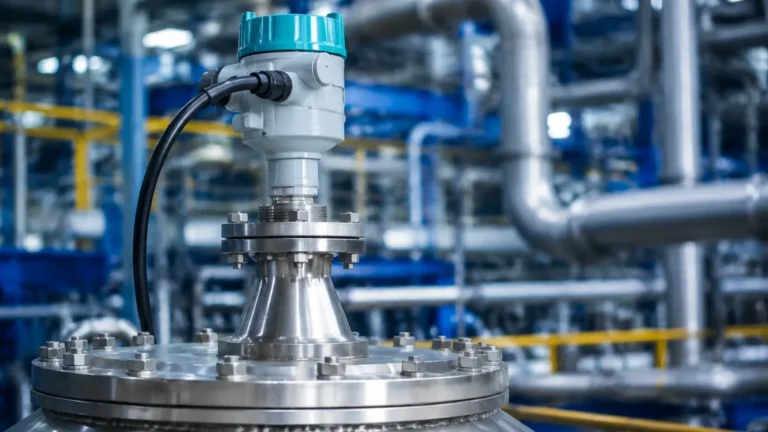
Advantages of Radar Level Transmitter
Advantages of Radar Level Transmitter: A Technical Engineering Guide
In the landscape of industrial process automation, precise level measurement is a cornerstone of operational safety, inventory management, and process efficiency. Among the various technologies available, Radar Level Meters have emerged as the gold standard for challenging environments. This article examines the fundamental measurement principles, the technical advantages of radar level transmitter systems, and the engineering considerations necessary for successful deployment in B2B industrial applications.
Understanding Radar Measurement Principles
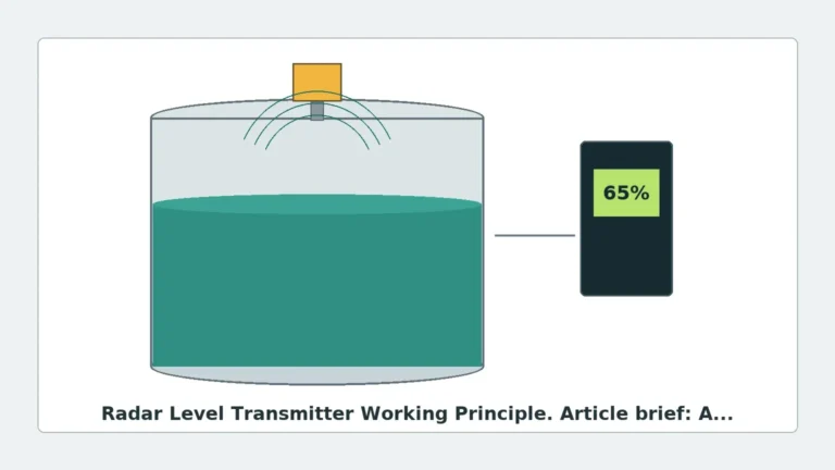
Before evaluating the specific benefits, it is essential to understand how radar technology interfaces with process media. Radar level transmitters utilize electromagnetic waves, typically in the microwave spectrum, to determine the distance to a product surface. Unlike ultrasonic sensors that rely on sound waves (mechanical energy), radar signals travel at the speed of light and do not require a medium for propagation.
There are two primary methods used in industrial radar measurement:
1. Pulse Radar (Time of Flight)
Pulse radar transmitters emit a short microwave signal toward the medium. The instrument measures the time interval between the emission of the pulse and the reception of the reflected echo. Since the speed of light is constant, the distance is calculated as:
*Distance = (Speed of Light × Time of Flight) / 2*
2. Frequency Modulated Continuous Wave (FMCW)
Modern high-precision radar transmitters often utilize FMCW technology. Instead of discrete pulses, the transmitter emits a continuous signal with a constantly changing frequency (a frequency sweep). The reflection from the product surface is received and compared to the signal being emitted at that moment. The frequency difference between the transmitted and received signals is directly proportional to the distance. FMCW is generally preferred for its higher accuracy and better signal-to-noise ratio, particularly in 80 GHz high-frequency units.
The Core Advantages of Radar Level Transmitter Systems
The transition from mechanical or contact-based measurement to radar technology is driven by several distinct engineering advantages that improve reliability and reduce long-term operational costs.
Non-Contact Measurement
One of the most significant advantages of radar level transmitter technology is its non-contact nature. The sensor does not touch the process media, which is critical when dealing with corrosive, viscous, or abrasive substances. This eliminates the risk of sensor degradation due to chemical attack or mechanical wear, significantly extending the lifespan of the instrument compared to float switches or displacers.
Immunity to Environmental Variables
Because radar utilizes electromagnetic waves, it is largely unaffected by the physical properties of the vapor space above the liquid or solid.
- Temperature and Pressure: Radar signals are stable in temperatures ranging from cryogenic levels to over 400°C and can operate in vacuum conditions or high-pressure environments (up to 160 bar or more).
- Vapor and Dust: Unlike ultrasonic sensors, which can be attenuated by heavy dust or steam, radar waves penetrate these obstacles with minimal loss, ensuring a consistent signal even in heavy boiling or pneumatic filling conditions.
- Gas Composition: Changes in the gas mixture (e.g., nitrogen blanketing or high CO2 concentrations) do not change the speed of the radar signal, maintaining calibration accuracy.
High Precision and Repeatability
Modern Radar Level Meters offer millimetric accuracy (often ±1mm or ±2mm). This level of precision is vital for custody transfer and high-value chemical processing where small errors in level measurement translate to significant financial discrepancies.
Versatility Across Media
Radar transmitters are effective for both liquids and bulk solids. They can measure everything from clean water and fuels to aggressive acids and fine powders. While the dielectric constant ($ε_r$) of the material affects the strength of the reflection, advanced signal processing allows radar to track materials with very low reflectivity.
Technical Selection Criteria for Industrial Applications
Selecting the right radar transmitter requires a detailed analysis of the process conditions. Engineers should focus on the following parameters:
Frequency Selection
- 6 GHz to 10 GHz (C-Band): Best for applications with heavy foam, steam, or extreme turbulence, as the longer wavelength can penetrate these surface disturbances.
- 24 GHz to 26 GHz (K-Band): The standard "all-rounder" for most industrial tanks. It offers a good balance between beam focus and signal strength.
- 80 GHz (W-Band): Provides the narrowest beam angle and highest resolution. It is ideal for small tanks with internal obstructions or for measuring solids where the surface may be uneven.
Antenna Design
The antenna serves as the interface between the electronics and the process. Common types include:
- Horn Antennas: Robust and suitable for most large vessels.
- Lens Antennas: Often used in 80 GHz units; they are flush-mounted and highly resistant to condensation or buildup.
- Drip-off/PTFE Encapsulated: Designed for highly corrosive environments where the antenna must be protected from chemical vapors.
Comparative Analysis: Radar vs. Other Technologies
| Feature | Radar (Non-Contact) | Ultrasonic | Hydrostatic | Guided Wave Radar (GWR) |
| :— | :— | :— | :— | :— |
| Measurement Type | Non-contact | Non-contact | Contact (Pressure) | Contact (Probe) |
| Vacuum Suitability | Excellent | Not Possible | Good | Excellent |
| Dust/Steam Resistance | High | Low | N/A | High |
| Accuracy | High (±1-2mm) | Medium (±5-10mm) | Medium (Density dependent) | High (±2mm) |
| Maintenance | Very Low | Low | Moderate | Moderate (Probe cleaning) |
| Media Density Impact | None | None | High | None |
Installation Engineering Guidelines
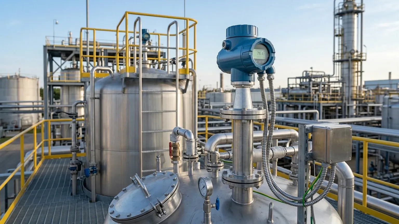
To fully realize the advantages of radar level transmitter performance, proper installation is mandatory. Incorrect placement can lead to "false echoes" and signal loss.
1. Avoid the Tank Wall: The transmitter should not be mounted too close to the tank wall. The beam expands as it travels; if it hits the wall, the resulting reflection can interfere with the true level signal. A general rule is to maintain a distance of at least 200mm to 500mm from the wall, depending on the beam angle.
2. Nozzle Considerations: The antenna should ideally extend slightly past the bottom of the mounting nozzle to prevent internal reflections within the nozzle neck. If using a long nozzle, a radar unit with a narrower beam (higher frequency) is required.
3. Obstruction Clearance: Identify internal structures such as agitators, heating coils, or ladders. While modern software can "map out" these static reflections (False Signal Suppression), it is best practice to install the sensor where the beam has a clear path to the product surface.
4. Inlet Streams: Never mount the radar directly over the filling inlet. The turbulence and the falling material will create significant noise and may lead to erratic readings.
Operational Limitations and Mitigation
While radar is highly versatile, engineers must account for specific limitations:
- Low Dielectric Constants: Materials with a dielectric constant ($ε_r$) below 1.4 (such as certain liquefied gases) reflect very little energy. In these cases, Guided Wave Radar (GWR) or a stilling well may be necessary to concentrate the signal.
- Heavy Foam: While C-band radar can penetrate some foam, extremely dense, thick foam (like shaving cream) can absorb the microwave signal entirely. Selecting a lower frequency or utilizing a GWR probe can mitigate this.
- Agitation and Turbulence: Rapidly moving surfaces can scatter the radar signal. High-frequency FMCW radar with rapid sampling rates and advanced averaging algorithms is the best solution for turbulent reactors.
Buyer’s Checklist for International Procurement
When sourcing Radar Level Meters for global projects, B2B buyers should confirm the following technical specifications with the manufacturer:
1. Certifications: Does the unit meet ATEX, IECEx, or SIL2/3 safety requirements for hazardous areas?
2. Process Connection: Are the flange standards compatible (ANSI, DIN, JIS)?
3. Output Protocols: Does the facility require 4-20mA HART, Modbus RTU, Profibus, or Foundation Fieldbus?
4. Material Compatibility: Is the wetted material (e.g., 316L Stainless Steel, Hastelloy, PTFE) compatible with the process chemical profile?
5. Minimum Dielectric Constant: What is the lowest $ε_r$ the device can reliably measure at the required range?
Frequently Asked Questions (FAQ)
Q: Can radar level transmitters measure through plastic tank walls?
A: Yes, certain frequencies can penetrate non-conductive materials like plastic or glass, allowing for measurement from outside the tank without a process penetration.
Q: How does condensation affect radar performance?
A: While condensation on the antenna can attenuate the signal, lens-shaped antennas made of PTFE are designed to allow droplets to run off, minimizing the impact. 80 GHz units are particularly resilient to light buildup.
Q: Is calibration required for different liquids?
A: No. Since radar measures distance based on the speed of light, it does not need to be recalibrated if the liquid density or conductivity changes, provided the dielectric constant remains above the minimum threshold.
Q: What is the "Dead Zone" or "Blocking Distance"?
A: This is the area immediately below the antenna where the device cannot accurately measure. It typically ranges from 50mm to 300mm depending on the model. This must be accounted for in the tank's high-level alarm settings.
Conclusion
The technical advantages of radar level transmitter systems—ranging from their non-contact operation to their immunity against temperature and pressure fluctuations—make them an indispensable tool in modern industrial engineering. By selecting the appropriate frequency and antenna type, and adhering to strict installation guidelines, plants can achieve high-precision level monitoring with minimal maintenance requirements. For engineers and procurement specialists, investing in high-quality radar technology is a strategic decision that enhances both the safety and the profitability of the process environment.