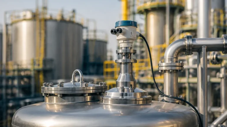
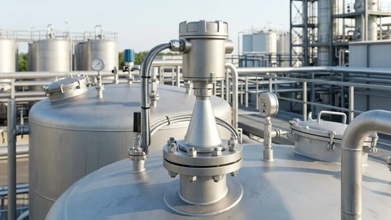
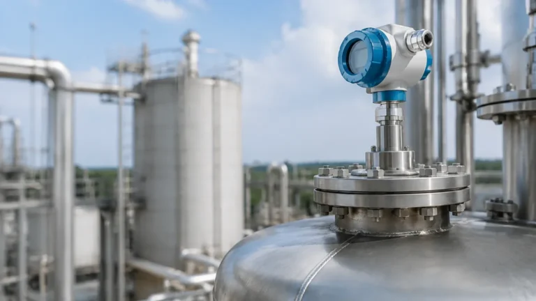
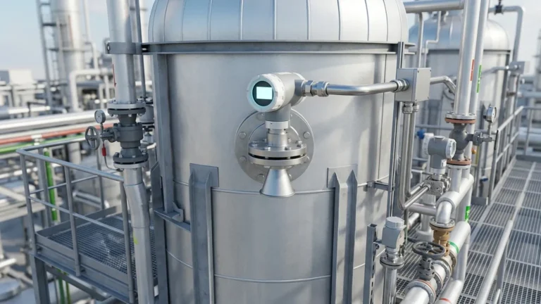
Abb Non Contact Radar Level Transmitter
Engineering Guide to Non-Contact Radar Level Transmitters
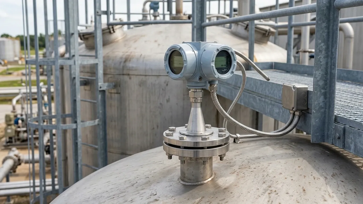
In the landscape of industrial process automation, the demand for precise, maintenance-free level measurement has led to the widespread adoption of non-contact radar technology. Instruments like the ABB non contact radar level transmitter have set industry benchmarks for reliability in challenging environments, ranging from corrosive chemical storage to high-temperature oil processing. This guide examines the fundamental engineering principles, selection criteria, and installation best practices for integrating radar level meters into modern industrial workflows.
Measurement Principles of Radar Level Technology
Non-contact radar level transmitters operate on the principle of "Time of Flight" (ToF) using electromagnetic waves in the microwave spectrum. Unlike ultrasonic sensors, which rely on sound waves and are susceptible to air temperature and pressure changes, radar signals travel at the speed of light and are largely unaffected by the vapor space medium.
Frequency Modulated Continuous Wave (FMCW)
Modern high-performance transmitters, including many in the ABB portfolio, typically utilize Frequency Modulated Continuous Wave (FMCW) technology. In an FMCW system, the transmitter emits a continuous signal with a constantly changing frequency. When the signal reflects off the material surface and returns to the antenna, it is compared with the frequency being emitted at that exact moment. The frequency difference ($Δf$) is directly proportional to the distance the signal has traveled.
Pulse Radar
Older or simpler radar systems may use Pulse Radar, where short bursts of microwave energy are emitted. The sensor measures the time interval between the pulse emission and the reception of the echo. While effective for basic liquid applications, pulse radar often lacks the signal-to-noise ratio required for complex environments with heavy foam or dust.
The Role of Frequency (6GHz to 80GHz)
The frequency of the microwave signal determines the beam angle and the ability of the sensor to handle signal attenuation.
- 80 GHz Radar: Offers a very narrow beam angle (often as low as 3°), making it ideal for tall, narrow vessels or tanks with internal obstructions like agitators and heating coils.
- 26 GHz Radar: A versatile mid-range frequency suitable for most standard liquid and solid applications.
- 6 GHz Radar: Used primarily in applications with heavy foam or turbulent surfaces, as the longer wavelength can penetrate surface disturbances more effectively.
Selection Criteria for Industrial Radar Level Meters
Choosing the correct Radar Level Meters requires a thorough analysis of the process media and the vessel geometry. Engineers must consider the dielectric constant ($ε_r$) of the material, as this determines how much energy is reflected back to the sensor.
Material Properties and Dielectric Constant
The dielectric constant is a measure of a material's ability to reflect microwave energy. Hydrocarbons (oils, fuels) have low dielectric constants (typically 1.9 to 4.0), while water-based liquids have high constants (up to 80). For materials with very low $ε_r$, a more sensitive antenna or a guided wave radar might be necessary, though high-frequency non-contact units are increasingly capable of measuring these fluids.
Selection Table: Radar Technology Comparison
| Feature | 80 GHz (High Frequency) | 26 GHz (Standard) | 6 GHz (Low Frequency) |
| :— | :— | :— | :— |
| Beam Angle | 3° – 8° | 10° – 20° | >20° |
| Typical Accuracy | ±1 mm (0.04 in) | ±3 mm (0.12 in) | ±10 mm (0.4 in) |
| Max Range | Up to 120 m | Up to 30 m | Up to 20 m |
| Dust/Vapor Resistance | Excellent | Good | Fair |
| Foam Penetration | Low | Moderate | High |
| Best For | Narrow tanks, solids, precision | General liquid storage | Turbulent liquids, heavy foam |
Installation Considerations and Constraints
Correct physical installation is the most critical factor in ensuring the long-term accuracy of an ABB non contact radar level transmitter. Even the most advanced signal processing cannot fully compensate for a poorly positioned sensor.
Nozzle Geometry
The mounting nozzle should be as short and wide as possible. If a nozzle is too long or narrow, the radar signal may reflect off the internal walls of the nozzle, creating a "ringing" effect or a large dead zone at the top of the tank. For 80 GHz sensors, nozzle interference is significantly reduced due to the narrow beam, but it remains a factor for lower-frequency units.
Obstruction Avoidance
The radar beam expands as it travels. Engineers must calculate the beam diameter at the bottom of the tank to ensure it does not hit ladders, agitator blades, or stay pipes. If obstructions are unavoidable, most modern transmitters offer "False Echo Suppression" software, which allows the user to map out static reflections and ignore them during measurement.
Positioning Rules
1. Distance from Wall: Sensors should typically be mounted at 1/6th of the tank diameter away from the wall to avoid interference from wall seams or build-up.
2. Avoid the Center: Never mount a radar sensor in the exact center of a domed-roof tank, as the roof shape can focus parasitic reflections back to the antenna.
3. Inlet Streams: Ensure the sensor is not positioned directly above the product inlet, as the falling stream will cause erratic readings.
Limitations and Application Risks
While non-contact radar is highly versatile, it is not a universal solution. Certain process conditions can degrade performance:
* Heavy Foam: Dense, thick foam (like shaving cream) can absorb the radar signal entirely, leading to a "Loss of Echo" (LoE) error. In these cases, low-frequency radar or guided wave radar is preferred.
* Extreme Turbulence: Rapidly moving liquid surfaces can scatter the signal. While software filtering helps, it may slow down the response time of the instrument.
* Condensation and Buildup: While many antennas are designed with PTFE droplet covers, heavy coating or crystallization on the antenna lens will eventually attenuate the signal. Periodic cleaning or the use of a purging connection (using compressed air or nitrogen) may be required.
* Vacuum and Pressure: While the radar signal itself is unaffected by vacuum, the mechanical seals of the transmitter must be rated for the specific process pressure and temperature. High-pressure steam applications often require specialized signal compensation due to changes in the vapor space density.
Maintenance and Calibration
One of the primary advantages of non-contact radar is the lack of moving parts. Maintenance is generally limited to visual inspections of the antenna and verifying the electronics via the 4-20mA HART, Modbus, or Profibus output.
Calibration is typically performed "dry" by entering the tank height and the desired measurement range into the transmitter's software. Unlike hydrostatic transmitters, radar does not require a full-tank/empty-tank physical calibration, which significantly reduces commissioning time and safety risks for technicians.
Frequently Asked Questions (FAQ)
Q: Can a non-contact radar measure through a plastic tank lid?
A: Yes. Since microwaves can penetrate non-conductive materials like polyethylene or fiberglass, the sensor can be mounted outside the tank, looking through a window or the tank roof, provided the material is not reinforced with metal fibers.
Q: What is the "Blocking Distance"?
A: The blocking distance (or Dead Zone) is the area immediately below the antenna where the transmitter cannot accurately measure. This is usually between 50 mm and 300 mm, depending on the frequency and antenna design. The tank should be managed so the liquid level does not enter this zone.
Q: How does the dielectric constant affect the update rate?
A: The dielectric constant does not directly affect the update rate, but for very low $ε_r$ materials, the transmitter may require more signal averaging to provide a stable reading, which can slightly increase the effective response time.
Q: Is 80 GHz always better than 26 GHz?
A: Not necessarily. While 80 GHz offers better focus and smaller antennas, 26 GHz or 6 GHz may be more robust in applications with heavy steam, condensation, or surface foam where a longer wavelength is more resilient against scattering.
Conclusion for International Buyers
When sourcing an ABB non contact radar level transmitter or equivalent industrial Radar Level Meters, buyers must provide the manufacturer with the specific dielectric constant of the medium, the vessel's internal drawing, and the maximum process temperature/pressure. Confirming these factual boundaries during the procurement phase ensures that the selected instrument provides the necessary accuracy (typically ±2mm or better) and operational longevity required for critical industrial infrastructure.