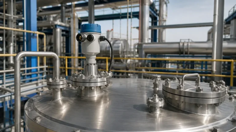
Antenna Type Radar Level Transmitter
Antenna Type Radar Level Transmitter: Engineering Principles and Selection Guide
In modern industrial process control, the accuracy and reliability of level measurement are fundamental to operational safety and efficiency. Among the various technologies available, the antenna type radar level transmitter has emerged as a preferred solution for non-contact measurement in both liquid and solid applications. By utilizing high-frequency electromagnetic waves, these instruments overcome many of the limitations associated with contact-based sensors, such as mechanical wear, corrosion, and material build-up.
This guide provides a comprehensive technical overview of Radar Level Meters, focusing on the operating principles of different antenna designs, selection criteria for industrial environments, and critical installation parameters.
1. Measurement Principles
An antenna type radar level transmitter operates on the principle of "Time of Flight" (ToF). The instrument's electronic component generates a high-frequency signal, which is emitted via the antenna toward the surface of the medium being measured. When the signal hits the surface, a portion of the energy is reflected back to the antenna. The transmitter then calculates the distance to the product surface based on the time delay between the transmission and reception of the signal.
Pulse Radar vs. FMCW
There are two primary modulation techniques used in industrial radar measurement:
* Pulse Radar: The transmitter emits a series of short microwave pulses. The time elapsed is measured directly. This method is generally energy-efficient and suitable for simpler applications.
* FMCW (Frequency Modulated Continuous Wave): The transmitter emits a continuous signal with a constantly changing frequency. The distance is determined by the frequency difference between the emitted and received signals at any given moment. FMCW, particularly at higher frequencies like 80GHz, offers superior resolution and accuracy, making it ideal for complex tank geometries or low-dielectric materials.
The Role of the Antenna
The antenna is the physical interface between the electronics and the process. Its primary function is to focus the electromagnetic energy into a narrow beam. A narrower beam angle reduces the risk of interference from tank walls, agitators, or internal bracing, thereby increasing the signal-to-noise ratio.
2. Types of Radar Antennas
Selecting the correct antenna type is critical for matching the instrument to the specific process conditions. The choice depends on the chemical compatibility, pressure, temperature, and the physical state of the medium.
Horn Antenna
The horn antenna is the most common design for liquid level measurement. It is typically constructed from stainless steel (e.g., 316L) and is suitable for a wide range of temperatures and pressures.
* Applications: Storage tanks, buffer tanks, and large vessels.
* Advantages: Robust, high gain, and available in various diameters to control beam angle.
Lens (Drop) Antenna
Lens antennas often feature a PTFE or PP cover that completely seals the antenna. This design provides a smooth, convex surface that resists condensation and material buildup.
* Applications: Corrosive chemicals, hygienic food and beverage processes, and environments with heavy steam.
* Advantages: Excellent chemical resistance and self-cleaning properties.
Rod Antenna
Rod antennas are slim and typically encased in a protective plastic sleeve (PTFE or PFA). They are designed for installation in small nozzles or narrow openings.
* Applications: Small chemical tanks or vessels with limited mounting space.
* Advantages: Compact footprint and high chemical resistance.
Parabolic Antenna
For long-range measurements, particularly in solids like grain or cement silos, parabolic antennas are used. The large surface area of the parabola focuses the signal into an extremely narrow beam.
* Applications: Large silos, outdoor stockpiles, and distances exceeding 30 meters.
* Advantages: Highest signal gain and narrowest beam angle.
3. Selection Criteria and Technical Specifications
When specifying an antenna type radar level transmitter, engineers must evaluate several environmental and material factors. The following table summarizes the primary selection considerations:
| Factor | Impact on Selection | Engineering Consideration |
| :— | :— | :— |
| Dielectric Constant ($ε_r$) | Signal Reflection Strength | Low $ε_r$ materials (e.g., oils) require higher sensitivity or larger antennas. |
| Process Temperature | Material Integrity | Standard antennas handle up to 150°C; high-temp versions reach 450°C+ with cooling fins. |
| Process Pressure | Mechanical Strength | Selection of flange rating (PN16, PN40, etc.) and high-pressure glass seals. |
| Vessel Height | Frequency & Gain | Higher frequencies (80GHz) are better for narrow/tall vessels; 26GHz for turbulent surfaces. |
| Medium State | Antenna Geometry | Solids require dust-resistant or aiming-capable antennas; liquids use horn or lens types. |
Dielectric Constant ($ε_r$)
The dielectric constant of the medium determines how much energy is reflected. Water has a high $ε_r$ (~80) and reflects signals strongly. Conversely, hydrocarbons like butane or plastic pellets have low $ε_r$ values (1.4 to 2.5), requiring more advanced signal processing and optimized antenna selection to ensure a reliable return echo.
4. Installation Guidelines and Constraints
Correct installation is as important as instrument selection. Even the most advanced antenna type radar level transmitter will fail if the signal path is obstructed or if the mounting geometry is incorrect.
Beam Angle and Obstructions
The radar beam spreads as it travels. The "footprint" of the beam at the bottom of the tank must be calculated to ensure it does not hit internal structures like ladders, heating coils, or agitators.
* Rule of Thumb: Maintain a minimum distance from the tank wall, typically 1/6th of the tank diameter.
* False Echo Suppression: Modern transmitters allow engineers to "map" the tank, telling the software to ignore reflections from fixed internal obstacles.
Nozzle Considerations
The antenna should ideally extend slightly beyond the mounting nozzle to prevent signal ringing or interference within the nozzle itself. If the nozzle is exceptionally long or narrow, a lens antenna or a specific nozzle-extension horn may be required.
Orientation and Leveling
For liquid applications, the antenna must be mounted perpendicular to the liquid surface. For solid applications, where the material forms a cone (angle of repose), an adjustable flange or aiming device is often necessary to direct the beam toward the material for maximum reflection.

5. Limitations and Application Risks
While highly versatile, radar technology is not a universal solution. Engineers should be aware of the following limitations:
1. Heavy Foam: Dense, conductive foam can absorb the radar signal entirely, leading to signal loss. In these cases, a guided wave radar or a differential pressure transmitter might be more appropriate.
2. Extreme Turbulence: Rapidly fluctuating surfaces can scatter the signal. This can often be mitigated by using software averaging or installing the transmitter in a bypass pipe or stilling well.
3. Vacuum Conditions: While radar works in a vacuum (unlike ultrasonic sensors), the mechanical seals of the antenna must be rated for vacuum to prevent air ingress or sensor damage.
4. Dust and Build-up: While non-contact, heavy coating on the antenna face can attenuate the signal. Air purging systems are often integrated into the antenna assembly for high-dust environments.
6. International Procurement: Buyer's Checklist
For international buyers and EPC contractors, ensuring compatibility with local standards and specific site requirements is vital. Before finalizing a purchase, confirm the following:
* Connection Standards: Ensure the flange or thread matches local standards (e.g., DN, ANSI, or JIS).
* Hazardous Area Certifications: Verify required ratings such as ATEX (Europe), IECEx (International), or UL/CSA (North America) for explosive atmospheres.
* Output Signals: Confirm the integration requirements, such as 4-20mA HART, RS485 Modbus, or Foundation Fieldbus.
* Material Certification: Request 3.1 material certificates for wetted parts if the application involves high-pressure or corrosive media.
7. Frequently Asked Questions (FAQ)
Q: Can a radar level transmitter measure through a plastic tank lid?
A: Yes, because plastic is non-conductive, radar signals can penetrate plastic or fiberglass covers, allowing for measurement without a tank opening, provided the material thickness is not excessive.
Q: What is the difference between 26GHz and 80GHz radar?
A: 80GHz radar has a much narrower beam angle and higher resolution, making it better for small tanks or vessels with many internal obstructions. 26GHz radar is often more robust in applications with heavy steam or dust.
Q: How often does an antenna type radar level transmitter need calibration?
A: Since there are no moving parts and the measurement is based on the speed of light (a physical constant), radar transmitters are extremely stable. Most industrial users perform a verification check annually, but full recalibration is rarely needed unless the electronics are replaced.
Conclusion
The antenna type radar level transmitter represents a pinnacle of non-contact level measurement technology. By understanding the nuances of antenna geometry, frequency, and process conditions, engineering teams can select a solution that provides maintenance-free operation for years. For complex applications involving extreme temperatures or low-dielectric materials, consulting with a specialized manufacturer like Welk ensures that the selected Radar Level Meters are optimized for the specific industrial environment.