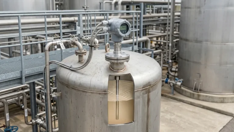
Emerson Guided Wave Radar Level Transmitter 5301
Engineering Guide to the Emerson Guided Wave Radar Level Transmitter 5301
In the field of industrial process automation, achieving precise and repeatable level measurement is critical for both operational efficiency and safety. Among the various technologies available, Guided Wave Radar (GWR) has emerged as a robust solution for challenging environments. The emerson guided wave radar level transmitter 5301 represents a high-performance 2-wire level transmitter designed for liquid applications, offering reliability in conditions where traditional measurement methods often fail.
This article provides a technical overview of the measurement principles, selection criteria, and installation requirements for the 5301 series, serving as a practical reference for instrumentation engineers and procurement professionals.
1. Measurement Principles of Guided Wave Radar
To understand the performance of the emerson guided wave radar level transmitter 5301, one must first understand the physics of Time Domain Reflectometry (TDR). Unlike non-contact Radar Level Meters that broadcast electromagnetic waves through the air, GWR systems guide a low-energy microwave pulse along a physical probe submerged in the process medium.
The TDR Process
1. Pulse Emission: The transmitter electronics generate a micro-pulse that travels down the probe at the speed of light.
2. Reflection: When the pulse encounters a change in the dielectric constant ($ε_r$)—typically at the interface between the air/gas and the process liquid—a portion of the energy is reflected back to the transmitter.
3. Time of Flight: The transmitter measures the time delay between the transmitted and received pulse. Since the speed of the pulse is constant, the distance to the product surface is calculated as:
*Distance = (Speed of Light × Time Delay) / 2*
4. Level Calculation: The level is determined by subtracting the measured distance from the known tank height (reference point).
Because the signal is concentrated around the probe, GWR is less susceptible to signal attenuation caused by foam, dust, or vapor compared to non-contact radar. Furthermore, the signal strength is significantly higher, allowing for the measurement of low-dielectric fluids with greater accuracy.
2. Technical Specifications and Performance Features
The Emerson 5301 is engineered to handle complex process conditions. Its design focuses on signal integrity through features such as Direct Switch Technology, which increases signal strength and improves the signal-to-noise ratio.
Key Performance Data
| Parameter | Specification (Metric/Imperial) |
| :— | :— |
| Measurement Range | Up to 50 m (164 ft) |
| Accuracy | ± 3 mm (0.12 in.) |
| Repeatability | ± 1 mm (0.04 in.) |
| Process Temperature | -196 to 400 °C (-320 to 752 °F) |
| Process Pressure | Full vacuum to 345 bar (5000 psi) |
| Minimum Dielectric | 1.2 (with coaxial probe) |
3. Probe Selection Criteria
The most critical component in specifying an emerson guided wave radar level transmitter 5301 is the probe. The choice of probe dictates the instrument's sensitivity and its ability to handle specific fluid characteristics such as viscosity and coating.
Coaxial Probes
Coaxial probes consist of an outer tube and an inner rod. The microwave pulse is completely contained within the tube.
* Advantages: Highest signal strength; unaffected by internal tank obstructions or narrow nozzles; suitable for very low dielectric fluids ($ε_r$ > 1.2).
* Limitations: Highly susceptible to clogging if the liquid is viscous or contains solids.
Single Lead Probes (Rigid or Flexible)
These consist of a single rod or cable. They are the most versatile for general industrial use.
* Advantages: Resistant to coating and build-up; easy to clean; ideal for viscous liquids.
* Limitations: Requires a larger "keep-out" zone from tank walls and internal obstructions; sensitive to electromagnetic interference if not installed correctly.
Twin Lead Probes
Twin probes use two parallel rods or cables.
* Advantages: Better signal strength than single lead; useful for longer ranges in clean liquids.
* Limitations: Prone to bridging between the leads if the fluid is dirty or prone to crystallization.
Probe Selection Summary Table
| Application Type | Recommended Probe | Dielectric Limit (ε_r) |
| :— | :— | :— |
| Clean, low-viscosity, low dielectric | Coaxial | > 1.2 |
| Viscous, coating, or dirty liquids | Single Rigid/Flexible | > 2.0 |
| Long range, clean liquids | Twin Flexible | > 1.9 |
| High-temperature/High-pressure | HTHP Coaxial/Single | Varies |
4. Installation Considerations and Constraints
Proper installation is paramount to ensuring the accuracy of the emerson guided wave radar level transmitter 5301. Engineers must account for the physical geometry of the vessel and the properties of the probe.
Nozzle Requirements
The diameter and height of the mounting nozzle can impact signal quality. For single lead probes, the nozzle should be as short as possible to prevent signal interference within the nozzle neck. If a tall nozzle is unavoidable, a coaxial probe or a probe with a dedicated centering disk may be required.
Clearance and Obstructions
Single and twin lead probes create an electromagnetic field around the leads. Any metallic object within this field (ladders, agitators, or the tank wall) can cause a false reflection.
* Single Lead Clearance: Maintain at least 100 mm (4 in.) from the tank wall and 300 mm (12 in.) from agitators.
* Coaxial Clearance: Zero clearance required; the outer tube acts as a shield.
Mounting Position
* Avoid the Center: Do not mount the transmitter in the exact center of a domed tank, as this can concentrate parasitic reflections.
* Inlet Proximity: Ensure the probe is not located directly in the path of the product inflow to prevent mechanical stress and signal noise.
* Stilling Wells and Bypass Chambers: GWR is exceptionally well-suited for use in bypass chambers. When replacing older displacer technology, the 5301 can often be retrofitted into existing cages, provided the probe type is matched to the cage diameter.

5. Application Risks and Limitations
While the emerson guided wave radar level transmitter 5301 is highly versatile, certain conditions can degrade its performance:
1. Extremely Low Dielectric Constants: If the fluid has a dielectric constant below 1.2, the reflected signal may be too weak to distinguish from background noise. In such cases, specialized Radar Level Meters with high-gain electronics are required.
2. Heavy Coating and Bridging: While single lead probes handle coating better than others, extreme build-up (e.g., dehydrated bitumen or heavy waxes) can cause "signal lost" errors or false high-level readings.
3. Heavy Turbulence: While GWR is more stable than non-contact radar in turbulent conditions, extreme physical movement of the fluid can cause flexible probes to swing, potentially hitting the tank wall or breaking. In these scenarios, rigid probes with end-of-probe anchoring are recommended.
4. Interface Measurement Limitations: For interface measurement (e.g., oil over water), the upper medium must have a lower dielectric constant than the lower medium, and the upper layer must be thick enough (typically > 100 mm) for the transmitter to resolve both peaks.
6. Comparison: Guided Wave vs. Non-Contact Radar
When selecting between GWR and non-contact radar, consider the following engineering trade-offs:
* Internal Obstructions: GWR is generally better for tanks with complex internals because the signal is confined to the probe path.
* Vapor and Foam: GWR performs significantly better in heavy steam or foam environments because the physical probe provides a direct path for the pulse, whereas non-contact pulses may be scattered or absorbed.
* Maintenance: Non-contact radar is often preferred for highly corrosive or extremely hygienic applications where the sensor should not touch the process medium. GWR, being a wetted technology, requires material compatibility checks for the probe and seals.
7. Frequently Asked Questions (FAQ)
Q: Can the probe of the 5301 be shortened in the field?
A: Yes, most rigid and flexible single-lead probes can be cut to length in the field. However, the transmitter configuration must be updated with the new probe length to maintain accuracy. Coaxial probes are more difficult to modify and should be ordered to the correct length.
Q: Does the transmitter require calibration with the actual process fluid?
A: No. One of the primary advantages of the emerson guided wave radar level transmitter 5301 is that it is a "dry" calibration device. As long as the dielectric constant and tank geometry are known, the device can be configured before installation.
Q: How does the 5301 handle vacuum conditions?
A: GWR is unaffected by vacuum because electromagnetic waves do not require a medium for travel. The 5301 is frequently used in vacuum distillation columns.
Q: What is the impact of a bent probe?
A: A slight bend in a single lead probe usually does not affect accuracy, but it may increase the risk of the probe contacting the tank wall. A bent coaxial probe can cause internal short-circuits of the microwave pulse and must be replaced.
8. Conclusion
The emerson guided wave radar level transmitter 5301 is a cornerstone of modern level measurement, offering a balance of precision and ruggedness. By understanding the interaction between the probe geometry and the dielectric properties of the process fluid, engineers can implement a solution that minimizes maintenance and maximizes uptime. For applications involving clean liquids, turbulent surfaces, or narrow bypass chambers, this GWR transmitter remains a preferred choice in the global industrial market.
When specifying equipment, always verify the chemical compatibility of the wetted parts (e.g., 316L Stainless Steel, Hastelloy, or PTFE) and ensure that the chosen probe length accounts for the full dynamic range of the vessel, including the dead zones at the top and bottom of the probe.
Download Emerson Guided Wave Radar Level Transmitter 5301 as a PDF