How Does a Guided Wave Radar Level Transmitter Work
How Does a Guided Wave Radar Level Transmitter Work: An Engineering Guide
In the landscape of industrial process control, accurate level measurement is a fundamental requirement for safety, efficiency, and inventory management. Among the various technologies available, Radar Level Meters have become a preferred choice due to their reliability in challenging environments. Specifically, Guided Wave Radar (GWR) technology offers a robust solution for both liquid and solid level detection.
Understanding how does a guided wave radar level transmitter work is essential for engineers and procurement professionals when selecting the right instrumentation for complex applications involving high pressure, varying temperatures, or low dielectric constants. This article provides a technical deep dive into the operating principles, selection criteria, and installation best practices for GWR transmitters.
The Core Principle: Time Domain Reflectometry (TDR)
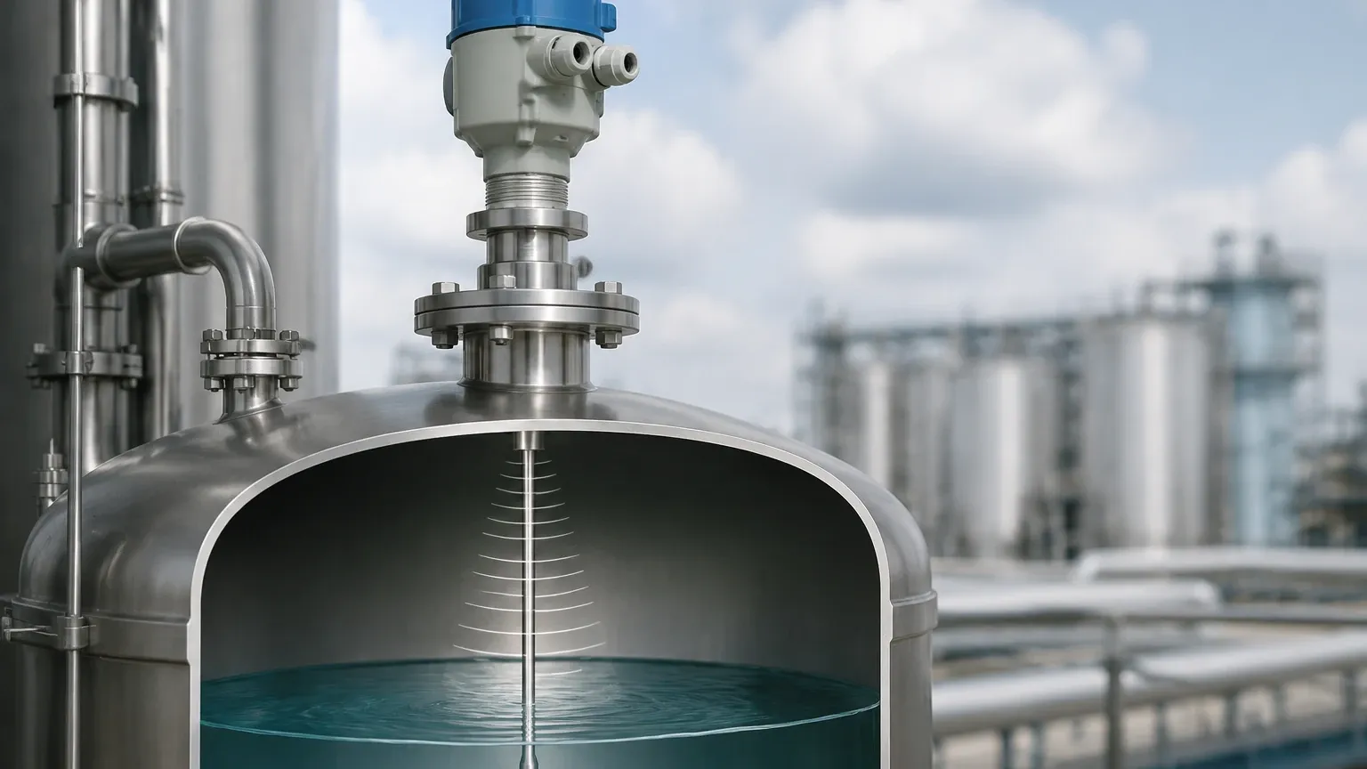
At the heart of every guided wave radar level transmitter is a technology known as Time Domain Reflectometry (TDR). While non-contact radar level meters emit electromagnetic waves through the air, GWR systems guide these waves along a physical probe—typically a metal rod, cable, or coaxial tube.
The Measurement Cycle
1. Pulse Emission: The transmitter's electronics generate low-energy, high-frequency microwave pulses.
2. Propagation: These pulses travel down the probe at the speed of light. Because the pulse is confined to the surface of the probe, the energy is concentrated, resulting in a stronger signal compared to non-contact radar.
3. Reflection: When the pulse encounters a change in the dielectric constant (εr) of the medium—such as the transition from air to a liquid or solid—a portion of the energy is reflected back up the probe.
4. Detection and Calculation: The transmitter’s sensor detects the reflected pulse. By measuring the precise time-of-flight (the time elapsed between emission and reception), the internal processor calculates the distance to the material surface using the formula:
*Distance = (Speed of Light × Time of Flight) / 2*
The Role of the Dielectric Constant
The dielectric constant (εr) of the medium is the most critical factor in determining signal strength. Air has a dielectric constant of 1.0. When a medium has a higher dielectric constant (e.g., water has an εr of approximately 80), a significant portion of the pulse is reflected. For materials with very low dielectric constants, such as certain oils or liquefied gases (εr < 2.0), the reflection is much weaker, requiring more sensitive electronics and specific probe configurations, such as coaxial probes, to ensure accuracy.
How Does a Guided Wave Radar Level Transmitter Work in Interface Measurement?
One of the unique advantages of GWR technology is its ability to measure interface levels—the boundary between two immiscible liquids, such as oil and water.
In an interface application, the first liquid (the upper layer) must have a lower dielectric constant than the second liquid (the lower layer). As the microwave pulse travels down the probe, it first encounters the upper layer. Because the upper layer has a low dielectric constant, only a small portion of the pulse is reflected (providing the total level), while the remainder of the energy continues through the upper liquid. When the pulse hits the second liquid with a higher dielectric constant, a second, stronger reflection occurs. This allows the transmitter to report both the total level and the interface level simultaneously.
Probe Selection and Application Suitability
Welk provides a variety of probe designs to accommodate different vessel geometries and material properties. Selecting the correct probe is vital for the performance of the radar level meter.
1. Single Rod/Cable Probes
These are the most common and cost-effective. They are ideal for liquids with high dielectric constants and are less prone to material build-up. However, they are more sensitive to electromagnetic interference from tank internals or the vessel wall.
2. Twin Rod/Cable Probes
Twin probes guide the pulse between two parallel conductors. This configuration provides a stronger signal than single rods and is suitable for measuring materials with lower dielectric constants over longer distances (up to 30 meters or approximately 98 feet).
3. Coaxial Probes
In a coaxial probe, the pulse is entirely contained within an outer tube. This offers the highest signal-to-noise ratio and is unaffected by tank obstructions, foam, or turbulence. It is the best choice for low-dielectric liquids and interface measurements.
| Feature | Single Rod | Twin Rod | Coaxial |
| :— | :— | :— | :— |
| Dielectric Range (εr) | > 1.9 | > 1.4 | > 1.2 |
| Max Range | Up to 6m (Rod) / 30m (Cable) | Up to 30m | Up to 6m |
| Build-up Resistance | High | Moderate | Low |
| Turbulence Resistance | Moderate | High | Excellent |
| Interface Measurement | Possible | Recommended | Best Choice |
Installation Considerations and Constraints
To ensure the accuracy of Radar Level Meters, engineers must adhere to specific installation guidelines. Failure to do so can result in signal loss or false echoes.
Nozzle Dimensions
The mounting nozzle should be as short and wide as possible. If the nozzle is too narrow or too long, it can create a "dead zone" or cause parasitic reflections that interfere with the surface signal. For GWR, the probe should extend at least 100 mm (4 inches) below the nozzle into the tank.
Clearance from Tank Walls and Internals
For single and twin rod probes, a minimum clearance from the tank wall is required to prevent signal interference. Typically, a distance of 300 mm (12 inches) is recommended. If the tank has agitators, heating coils, or ladders, the probe must be positioned to avoid physical contact and electromagnetic interference.
The "Dead Zone" (Upper and Lower Blocking Distances)
Every GWR transmitter has an upper and lower dead zone. The upper dead zone is the area near the mounting flange where the signal cannot be accurately resolved. The lower dead zone occurs at the end of the probe.
* Upper Dead Zone: Typically 50 mm to 200 mm (2 to 8 inches) depending on the probe and dielectric.
* Lower Dead Zone: Often 50 mm to 100 mm (2 to 4 inches).
Engineers must ensure that the maximum and minimum process levels fall within the "measurable range" between these two zones.
Limitations of Guided Wave Radar
While highly versatile, GWR is not a universal solution. Certain conditions can limit its effectiveness:
1. Heavy Material Build-up: While GWR handles thin coatings well, heavy, conductive build-up between twin rods or within a coaxial tube can bridge the conductors and cause the transmitter to report a static high-level signal.
2. Mechanical Stress: In tall silos containing heavy solids (like grain or cement), the pull-down forces on a cable probe can be immense, potentially damaging the tank roof or the transmitter mounting.
3. Physical Obstructions: Unlike non-contact radar, GWR requires a physical probe in the medium. This may not be suitable for highly corrosive or hygienic applications where a non-intrusive method is preferred.
Technical Comparison: GWR vs. Non-Contact Radar
| Parameter | Guided Wave Radar (GWR) | Non-Contact Radar |
| :— | :— | :— |
| Signal Strength | High (focused along probe) | Lower (dispersed through air) |
| Foam Impact | Minimal (penetrates most foam) | Significant (can absorb/scatter signal) |
| Obstructions | Must avoid physical contact | Must have clear line-of-sight |
| Installation | Requires probe immersion | Top-mounted, non-intrusive |
| Vacuum/Pressure | Excellent performance | Excellent performance |
| Vapor/Dust | Unaffected | Can be affected by heavy dust/steam |
Frequently Asked Questions (FAQs)
Q: Can GWR be used in plastic tanks?
A: Yes, but since plastic tanks do not provide a ground plane, GWR transmitters often require a "grounding plate" or a coaxial probe to function correctly. Single rod probes in plastic tanks may exhibit unstable readings without a proper reference ground.
Q: How does steam or high pressure affect the measurement?
A: GWR is largely unaffected by the gas phase composition. However, at very high pressures and temperatures (e.g., saturated steam applications), the speed of the microwave pulse through the gas can slow down slightly. High-end transmitters like those from Welk include "gas phase compensation" to automatically correct for this delay.
Q: Is it possible to shorten the probe in the field?
A: Most rod and cable probes can be shortened in the field. After cutting the probe to the desired length, the user must update the probe length setting in the transmitter software to recalibrate the time-of-flight calculation.
Q: What is the minimum dielectric constant required for GWR?
A: Most industrial GWR transmitters can measure down to a dielectric constant of 1.4 using twin or coaxial probes. Special high-sensitivity electronics can sometimes measure down to 1.2.
Conclusion
Guided Wave Radar technology represents a pinnacle of reliability for industrial level measurement. By guiding the microwave signal along a probe, GWR overcomes many of the limitations associated with non-contact measurement, such as foam, turbulence, and low-reflectivity surfaces.
When specifying a system, international buyers should confirm the dielectric constant of their medium, the potential for material build-up, and the mechanical constraints of the vessel. For professional-grade solutions tailored to water treatment, chemical processing, and oil and gas applications, Welk offers a range of Radar Level Meters designed to provide accurate data in the most demanding environments.
By carefully considering the probe type and installation environment, engineers can implement a level measurement solution that minimizes maintenance and maximizes process uptime.
Download How Does a Guided Wave Radar Level Transmitter Work as a PDF