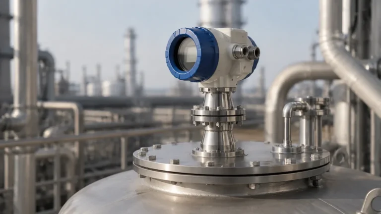
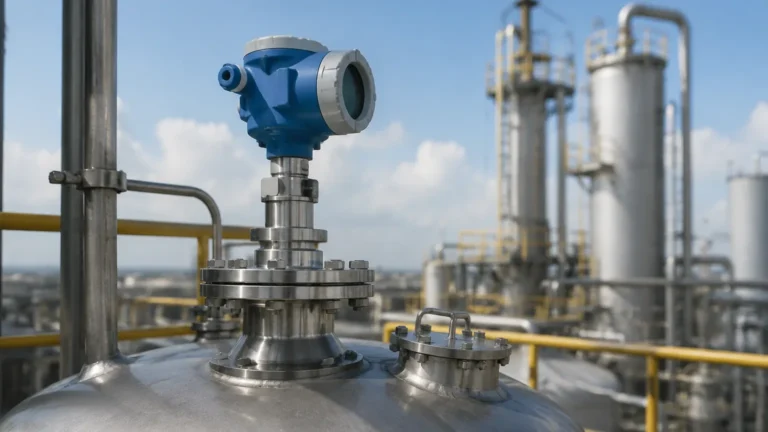
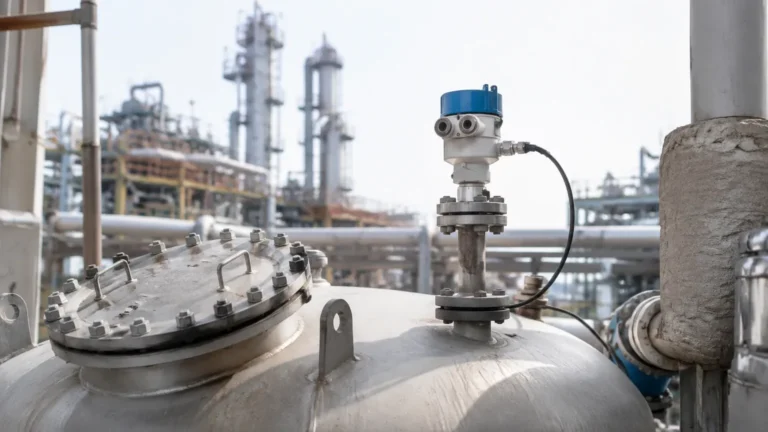
Radar Level Transmitter Flange
Radar Level Transmitter Flange: A Technical Engineering Guide to Selection and Installation
In industrial process control, the accuracy of level measurement is often determined not just by the electronics inside the sensor, but by the mechanical interface between the instrument and the vessel. For Radar Level Meters, the flange is the critical component that ensures process containment, signal integrity, and structural stability. Selecting the correct radar level transmitter flange requires a comprehensive understanding of microwave physics, metallurgy, and international piping standards.
This guide examines the engineering principles behind radar mounting, the technical specifications of various flange types, and the practical considerations necessary for ensuring reliable measurement in harsh industrial environments.
1. Measurement Principles and the Role of the Flange
Before selecting a mounting interface, it is essential to understand how radar technology interacts with the vessel. Radar level transmitters operate on either Pulse Radar (Time of Flight) or Frequency Modulated Continuous Wave (FMCW) principles. In both cases, the device emits electromagnetic waves toward the medium surface and measures the time taken for the echo to return.
The Signal Path
The radar signal is emitted through an antenna, which is typically housed within or attached to the flange assembly. The flange serves three primary functions:
1. Process Isolation: It maintains a pressure-tight and leak-proof seal between the internal vessel environment and the external atmosphere.
2. Signal Alignment: It ensures the antenna is perpendicular to the product surface (or correctly angled for solids) to maximize echo return.
3. Waveguide Transition: For certain antenna types, the flange acts as part of the waveguide transition, where the electromagnetic wave moves from the transmitter electronics into the free space of the tank.
If a radar level transmitter flange is incorrectly sized or positioned, it can create internal reflections (noise) within the mounting nozzle, leading to a "ringing" effect that masks the true level of the product, particularly when the tank is nearly full.
2. Types of Radar Level Transmitter Flanges
Flanges for radar transmitters are categorized by their mechanical design, material composition, and the specific standard they follow (such as ASME/ANSI or DIN/EN).
Standard Fixed Flanges
These are the most common interfaces, used where the nozzle is already perpendicular to the liquid surface. They are typically manufactured according to ASME B16.5 or EN 1092-1 standards. Common sizes range from DN50 (2") to DN200 (8"), with pressure ratings from PN10 up to PN100 (or Class 150 to Class 900).
Swivel (Aiming) Flanges
In applications involving bulk solids, such as grain, cement, or ore, the material forms a conical pile with a specific angle of repose. A standard fixed flange would point the radar beam straight down, potentially losing the signal as it reflects off the slope. A radar level transmitter flange with a swivel or gimbal mechanism allows the user to tilt the antenna (typically up to 15°) to align the beam perpendicular to the material slope, ensuring a strong return signal.
PTFE-Lined and Encapsulated Flanges
For highly corrosive chemical applications—such as hydrochloric acid or strong alkalis—the metallic surface of a 316L stainless steel flange may degrade. In these instances, the wetted parts of the flange and the antenna are encapsulated in PTFE (Polytetrafluoroethylene) or PFA. This provides a seamless, chemically inert barrier that protects the instrument while allowing the radar signal to pass through the plastic window with minimal attenuation.
3. Selection Criteria: Materials and Standards
Choosing the right radar level transmitter flange involves balancing chemical compatibility with mechanical strength requirements. The following table summarizes common material selections for industrial applications:
| Material | Temperature Range | Chemical Resistance | Typical Application |
| :— | :— | :— | :— |
| 316L Stainless Steel | -196°C to +400°C | Good (General) | Water treatment, oil, food & beverage. |
| Hastelloy C276 | -196°C to +400°C | Excellent (Acids) | Chemical processing, aggressive media. |
| PTFE Lined | -40°C to +200°C | Superior (Corrosives) | Strong acids, pickling tanks, ultrapure water. |
| Carbon Steel | -20°C to +250°C | Low | Non-corrosive oils, dry solids (low moisture). |
Pressure and Temperature Ratings
It is vital to confirm that the flange rating matches the vessel's Maximum Allowable Working Pressure (MAWP). For example, a Class 150 flange may be rated for 19 bar (285 PSI) at ambient temperature, but its pressure capacity drops significantly as the process temperature increases. Engineering teams must refer to the Pressure-Temperature (P-T) ratings defined in ASME B16.5 when specifying the flange for high-temperature reactors.
4. Installation Considerations and Nozzle Geometry
The performance of Radar Level Meters is heavily influenced by the geometry of the mounting nozzle. The flange must be installed in a way that minimizes interference.
Nozzle Height and Diameter
The "Nozzle Effect" is a common cause of measurement failure. If a nozzle is too long or too narrow, the radar beam will strike the interior walls of the nozzle before it even enters the tank. This creates a large "dead band" or "near-field" interference zone.
* Rule of Thumb: The nozzle height ($H$) should be as short as possible. Ideally, the antenna should extend at least 10 mm (0.4") beyond the bottom of the nozzle.
* Beam Angle: Every radar has a defined beam angle (e.g., 8° or 12°). The flange must be positioned so that the spread of the beam does not intercept the nozzle wall or internal tank obstructions like ladders or agitators.
Obstruction Avoidance
The flange should be located away from the tank wall to avoid multipath reflections. A common engineering standard is to mount the flange at a distance of 1/6th to 1/4th of the tank diameter from the wall, but never closer than 300 mm (12") to the wall to prevent signal degradation.

5. Application Risks and Limitations
While radar is a robust technology, certain process conditions can impact the effectiveness of the flange and antenna assembly:
1. Condensation and Buildup: In high-humidity applications, water droplets can form on the flange face or antenna. While modern 80GHz radars handle this better than older 6GHz models, heavy buildup can still attenuate the signal. Flanges with integrated purging ports allow for the injection of compressed air or nitrogen to keep the antenna face clean.
2. Foam: Heavy, dense foam can absorb radar signals. If foam is present, a larger flange and antenna size are often required to provide a higher gain signal to penetrate the foam layer.
3. Vacuum Seals: In vacuum distillation columns, the radar level transmitter flange must be equipped with a high-quality glass-to-metal seal or a dual-ceramic process seal to prevent vacuum loss and protect the transmitter electronics from process vapors.
6. Buyer’s Checklist: Confirming Specifications
When procuring a radar level transmitter, international buyers should confirm the following technical details with the manufacturer to ensure a correct mechanical fit:
* Flange Standard: Specify ASME B16.5 (North America), EN 1092-1 (Europe), or JIS B2220 (Japan).
* Nominal Size and Pressure Class: e.g., 3-inch Class 150 or DN80 PN16.
* Flange Face Type: Flat Face (FF), Raised Face (RF), or Ring Type Joint (RTJ). RF is the most common for industrial radar.
* Wetted Material: Confirm if the process requires 316L, Hastelloy, or a PTFE coating.
* Gasket Compatibility: Ensure the gasket material used between the transmitter flange and the vessel nozzle is compatible with the process medium.
* Certification Requirements: Determine if the project requires Material Traceability Reports (MTRs) or NACE MR0175 compliance for sour gas environments.
7. Frequently Asked Questions (FAQs)
Q: Can I use a smaller flange than the nozzle on my tank?
A: Yes, by using a reducer flange. However, ensure that the antenna can still pass through the narrower opening and that the beam angle does not hit the edges of the reducer.
Q: What is the benefit of an 80GHz radar regarding flange size?
A: Higher frequency radars (80GHz) have a much narrower beam angle. This allows for smaller flange sizes (down to 1 inch or DN25) while still avoiding interference from tank walls or nozzles.
Q: How do I handle a mounting nozzle that is not level?
A: You should utilize a swivel/aiming flange. This allows you to mechanically compensate for the nozzle's tilt and align the radar beam vertically toward the liquid surface.
Q: Is a plastic flange suitable for industrial radar mounting?
A: Plastic flanges (like PP or PVC) are often used in atmospheric water treatment tanks or chemical IBCs. However, they should not be used in pressurized applications or where temperatures exceed the plastic's structural limits.
Conclusion
The radar level transmitter flange is more than a simple mounting bracket; it is a precision-engineered component that facilitates accurate data acquisition. By adhering to proper piping standards, considering the dielectric properties of the medium, and respecting nozzle geometry constraints, engineers can ensure that their level measurement systems provide reliable service over a long operational lifespan. For complex applications involving high pressure or extreme corrosion, consulting with a manufacturer regarding customized flange solutions and material certifications is highly recommended.