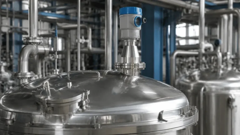
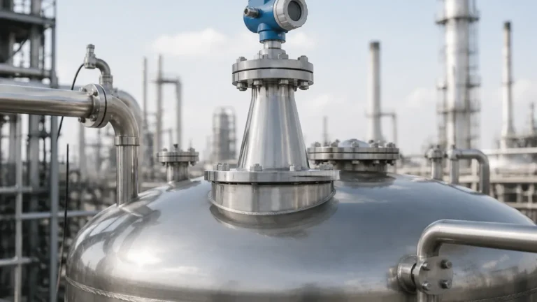
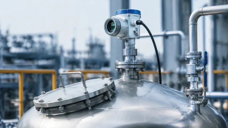
High Temperature Radar Level Transmitter
High Temperature Radar Level Transmitter: An Engineering Guide to Thermal Challenges and Solutions
In industrial process control, measuring the level of liquids or solids at extreme temperatures presents a significant engineering challenge. Standard level sensors often fail when exposed to the intense heat of molten metals, bitumen, hot oil, or pressurized chemical reactors. The high temperature radar level transmitter has emerged as the industry standard for these demanding environments, offering a non-contact solution that remains accurate where mechanical or contact-based systems degrade.
Modern Radar Level Meters utilize advanced microwave technology to penetrate vapors and withstand thermal radiation. However, selecting the right instrument requires a deep understanding of how high temperatures affect signal propagation, electronic longevity, and material integrity. This guide explores the principles, selection criteria, and installation strategies for high-temperature radar measurement.
1. Measurement Principles of Radar Level Meters
Radar level measurement is based on the "Time of Flight" (ToF) principle. The transmitter emits a high-frequency microwave signal toward the medium. This signal reflects off the surface and returns to the antenna. By measuring the time interval between emission and reception, the device calculates the distance to the product surface.
Pulse Radar vs. FMCW
There are two primary technologies used in radar level measurement:
* Pulse Radar: The device emits a short microwave pulse and measures the time it takes to return. While energy-efficient, it may struggle with low-reflectivity surfaces in high-heat environments where signal noise is prevalent.
* FMCW (Frequency Modulated Continuous Wave): The transmitter emits a continuous signal with a constantly changing frequency. The difference between the emitted and received frequency is proportional to the distance. FMCW is generally preferred for high-temperature applications because it provides a higher signal-to-noise ratio and better accuracy over long distances, even when the atmosphere inside the tank is turbulent or filled with vapors.
In high-temperature scenarios, the dielectric constant ($ε_r$) of the medium is a critical factor. As temperature rises, the dielectric constant of some liquids may change, affecting the strength of the reflected signal. A robust high temperature radar level transmitter must be calibrated to handle these fluctuations.
2. Engineering for Extreme Heat: Design Features
Standard radar electronics typically have an operating limit of approximately 60°C to 80°C (140°F to 176°F). To measure processes reaching 250°C, 400°C, or even 1,200°C (482°F to 2,192°F), Welk engineers utilize several specialized design features to protect the sensitive electronics from thermal damage.
Thermal Decoupling and Cooling Fins
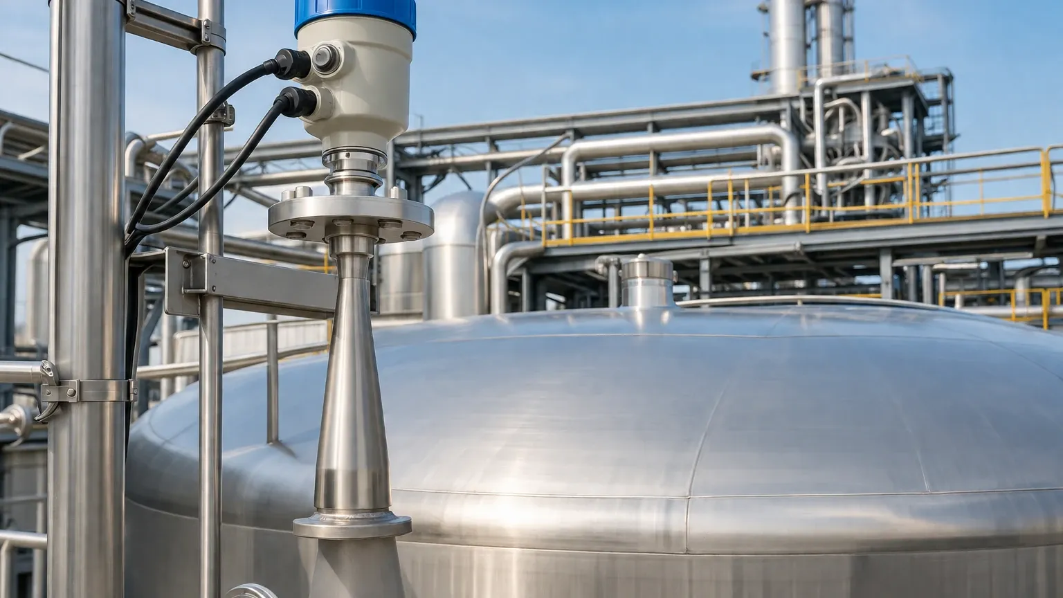
The most common method for protecting the transmitter head is thermal decoupling. By extending the distance between the process flange and the electronics housing, the heat has more space to dissipate. Cooling fins (heat sinks) are often integrated into the neck of the transmitter to increase the surface area for convective cooling, ensuring the internal electronics remain within their safe operating range.
Antenna Material Selection
The antenna is the only part of the radar meter directly exposed to the process environment. Material selection is paramount:
* PTFE (Teflon): Suitable for temperatures up to 200°C (392°F). It offers excellent chemical resistance.
* PEEK: Used for temperatures up to 250°C (482°F) and higher pressures.
* Ceramic (Alumina): Essential for extreme heat applications, such as molten glass or steel, where temperatures exceed 400°C (752°F). Ceramic lenses provide a robust hermetic seal and can withstand thermal shock.
Purging Systems
In high-temperature applications involving dust or heavy vapors (like cement kilns or chemical reactors), an air or nitrogen purging system is often added. This serves two purposes: it keeps the antenna face clean of deposits and provides a localized cooling effect to the lens.
3. Technical Selection Criteria
Choosing a high temperature radar level transmitter requires a detailed analysis of the process conditions. The following table provides a general framework for selection based on temperature and application type.
Selection Table: High-Temperature Radar Configurations
| Process Temperature | Recommended Antenna Type | Typical Materials | Common Applications |
| :— | :— | :— | :— |
| Up to 150°C (302°F) | Encapsulated Horn / Lens | PTFE, Stainless Steel | Food processing, wastewater |
| 150°C to 250°C (482°F) | Horn Antenna with Cooling Fins | PEEK, 316L SS | Hot oil, bitumen, chemical reactors |
| 250°C to 450°C (842°F) | Parabolic or Horn with Ceramic Seal | Ceramic, Graphite, Alloy | Power plants, steam drums, refinery units |
| Above 450°C (842°F) | Specialized Waveguide / Purged Lens | High-purity Ceramics | Molten metals, glass manufacturing |
Frequency Considerations
* 26 GHz Radar: Offers a wider beam angle, which is more forgiving of surface turbulence but may require larger nozzles. It is highly effective for solids and agitated liquids.
* 80 GHz Radar: Features a very narrow beam and smaller antenna size. This is ideal for high-pressure/high-temperature vessels with internal obstructions, as the narrow beam can easily avoid agitators or heating coils.
4. Installation Considerations for High-Heat Environments
Correct installation is as vital as the instrument selection itself. In high-temperature applications, the physical mounting of the radar level meter can determine whether the device lasts for years or fails in weeks.
Nozzle and Standoff Pipe Design
When dealing with extreme heat, the nozzle (the pipe connecting the transmitter to the vessel) acts as a chimney. If the nozzle is too short, the electronics will be exposed to direct radiant heat. Engineering best practices suggest using a standoff pipe to elevate the transmitter. However, the pipe must be designed to avoid internal reflections (parasitic signals) that could interfere with the radar wave.
Insulation and Heat Tracing
While it may seem counterintuitive, insulating the vessel flange is often necessary to prevent condensation on the antenna. If the process is hot but the transmitter flange is cold, vapors may condense and solidify on the lens, blocking the signal. However, the electronics housing itself must never be insulated; it requires airflow to stay cool.
Beam Path Clearance
High-temperature vessels often contain internal structures like heating coils or baffles. Because heat can cause these structures to expand or shift, the radar beam path must have sufficient clearance. Using an 80 GHz high temperature radar level transmitter is often the best solution here, as its 3-degree beam angle minimizes the risk of false echoes from internal tank hardware.
5. Limitations and Application Risks
Despite their robustness, radar level meters face specific limitations in high-temperature environments:
1. Vapor Phase Influence: In extremely high-pressure steam applications, the heavy vapor phase can actually slow down the speed of the radar wave. This results in a "propagation delay," where the distance measured appears slightly longer than it actually is. Advanced transmitters allow for a vapor compensation factor to be programmed into the software.
2. Dielectric Constant Shift: As temperatures approach the critical point of a liquid, its dielectric constant typically drops. If the $ε_r$ falls below 1.4, the reflected signal may become too weak to detect without a specialized high-sensitivity antenna.
3. Thermal Expansion: In very tall tanks, the thermal expansion of the vessel itself can introduce a small margin of error in the level reading. For high-precision applications, this must be accounted for in the control system logic.
6. Maintenance and Lifecycle Management
For a high temperature radar level transmitter, maintenance is primarily focused on the antenna and the cooling system.
* Visual Inspection: Periodically check the cooling fins for dust buildup, which can act as insulation and cause the electronics to overheat.
* Purge Verification: If a nitrogen purge is used, ensure the flow rate is consistent. A drop in purge pressure can lead to lens coating or overheating.
* Signal Diagnostics: Modern Welk radar units provide signal-to-noise ratio (SNR) diagnostics. A gradual decrease in SNR often indicates buildup on the antenna or a degrading seal, allowing for predictive maintenance before a total failure occurs.
7. Frequently Asked Questions (FAQ)
Q: Can a radar level meter work in a vacuum at high temperatures?
A: Yes. Since radar waves do not require a medium to travel (unlike ultrasonic waves), they function perfectly in a vacuum. However, the seal between the antenna and the process must be rated for both the vacuum and the high temperature.
Q: How do I protect the transmitter from radiant heat from the tank surface?
A: Use a heat shield or a longer standoff pipe. A simple polished stainless steel plate mounted between the flange and the electronics can reflect a significant portion of radiant heat away from the sensor head.
Q: Is 80 GHz always better than 26 GHz for high temperatures?
A: Not necessarily. While 80 GHz allows for smaller nozzles and better focus, 26 GHz is often more robust in applications with heavy steam or very thick dust, as the longer wavelength can penetrate these obstacles more effectively.
Q: What information should I provide when requesting a quote?
A: An international buyer should confirm the maximum process temperature, operating pressure, the chemical composition of the medium (to check material compatibility), the dielectric constant, and the nozzle dimensions (height and diameter).
Conclusion
The implementation of a high temperature radar level transmitter is a strategic investment in process safety and efficiency. By understanding the interplay between microwave physics and thermal engineering, plant managers can ensure reliable level monitoring in even the most hostile industrial environments. Whether managing molten glass or high-pressure chemical synthesis, Welk's range of Radar Level Meters provides the precision and durability required for modern industrial automation. Proper selection, focused on antenna materials and thermal decoupling, remains the cornerstone of a successful high-temperature installation.