How Does a Radar Level Transmitter Work
How Does a Radar Level Transmitter Work: A Technical Engineering Guide
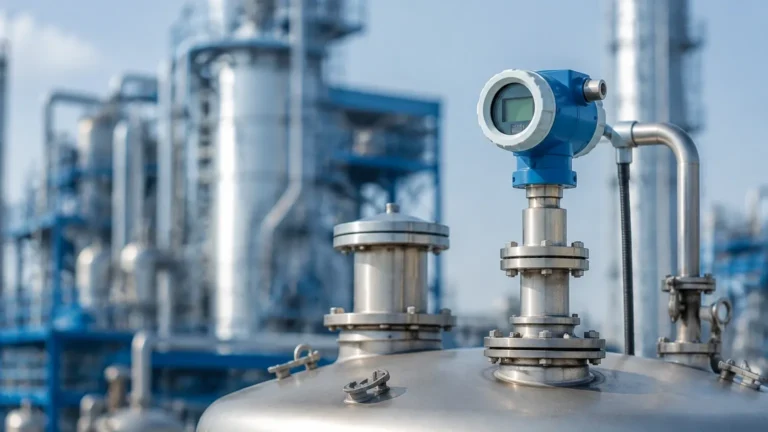
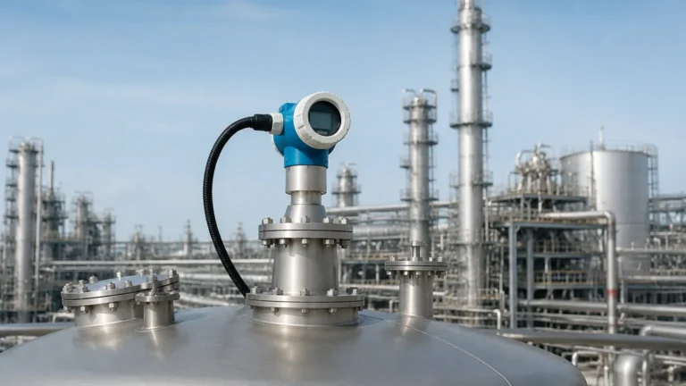
In modern industrial process control, accurate level measurement is critical for safety, inventory management, and process efficiency. Among the various technologies available, Radar Level Meters have emerged as a leading solution due to their non-contact nature and reliability in harsh environments. Understanding the underlying physics and engineering principles of these devices is essential for proper selection and installation. This guide explores the fundamental question: how does a radar level transmitter work, while providing practical insights for industrial applications.
Core Measurement Principles
Radar level measurement is based on the propagation of electromagnetic waves. Unlike ultrasonic sensors, which use sound waves that require a medium (air) and are affected by temperature and pressure, radar waves are microwaves that travel at the speed of light and are largely unaffected by atmospheric conditions.
Time of Flight (ToF)
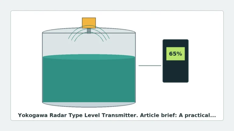
At its simplest, a radar transmitter operates on the Time of Flight principle. The device emits a high-frequency microwave signal toward the surface of the medium. When the signal hits the surface, a portion of the energy is reflected back to the sensor's antenna. By measuring the time interval ($t$) between transmission and reception, the distance ($D$) can be calculated using the constant speed of light ($c$):
$$D = \frac{c \times t}{2}$$
The level of the material is then determined by subtracting the measured distance from the total tank height (the calibration zero point).
Pulse Radar vs. FMCW
There are two primary methods used by industrial radar transmitters to process this signal:
1. Pulse Radar: The transmitter sends out short microwave pulses and waits for the return signal. It is energy-efficient and suitable for simple liquid level applications. However, it may struggle with low-dielectric materials or turbulent surfaces where the echo is weak.
2. Frequency Modulated Continuous Wave (FMCW): Instead of pulses, the transmitter emits a continuous signal with a constantly changing frequency (a frequency sweep). The reflection is received while the transmitter is still emitting. The difference in frequency between the emitted and received signals is proportional to the distance. FMCW offers much higher resolution and signal-to-noise ratios, making it the preferred choice for solids, powders, and complex liquid processes.
How Does a Radar Level Transmitter Work? Step-by-Step
To understand how does a radar level transmitter work in a practical field environment, we must look at the internal process from signal generation to digital output.
1. Signal Generation and Emission
The electronic circuit within the transmitter housing generates a microwave signal, typically in the K-band (26 GHz) or W-band (80 GHz). This signal is directed through the antenna—which may be a horn, a rod, or a lens—into the vessel.
2. Propagation and Reflection
The microwaves travel through the vapor space of the tank. When they encounter a change in the dielectric constant (relative permittivity, $\epsilon_r$), a reflection occurs. The dielectric constant of the material being measured determines how much energy is reflected. Materials with high $\epsilon_r$, such as water ($\epsilon_r \approx 80$), provide strong reflections. Non-conductive materials like oils or plastics ($\epsilon_r < 3$) reflect very little energy, requiring more sensitive electronics.
3. Signal Reception and Filtering
The antenna receives the reflected echo. In industrial environments, the antenna also receives "false echoes" from internal tank structures like agitators, heating coils, or ladders. Modern radar level meters utilize advanced Digital Signal Processing (DSP) and "Echo Mapping" software to identify and ignore these static obstructions, focusing only on the moving surface level.
4. Data Conversion and Output
Once the distance is calculated, the transmitter converts this value into an industrial signal, such as a 4-20mA analog loop, HART, Modbus, or Profibus, which is then sent to a PLC (Programmable Logic Controller) or DCS (Distributed Control System).
Non-Contact vs. Guided Wave Radar
While non-contact radar is standard, Guided Wave Radar (GWR) is a significant variant used in specific industrial scenarios.
* Non-Contact Radar: The signal travels through the air. It is ideal for corrosive liquids, high temperatures, and applications where the sensor must not touch the medium.
* Guided Wave Radar (GWR): The microwave pulse travels along a physical probe (a rod or cable) dipped into the medium. This concentrates the energy, making it highly effective for materials with very low dielectric constants or in applications with heavy foam and steam that might disperse a free-space signal.
Technical Selection Criteria
Choosing the right radar level meter requires balancing process conditions with instrument specifications. The following table summarizes the primary considerations for B2B procurement and engineering design.
| Feature | 26 GHz Radar | 80 GHz Radar | Guided Wave Radar (GWR) |
| :— | :— | :— | :— |
| Best Application | General liquid storage, large tanks | Small tanks, solids, high precision | Low Dk liquids, bypass chambers, foam |
| Beam Angle | Moderate (approx. 8°–12°) | Narrow (approx. 3°–4°) | N/A (signal follows probe) |
| Accuracy | ±3 mm to ±5 mm | ±1 mm | ±2 mm |
| Max Range | Up to 30–70 meters | Up to 120 meters | Up to 30–60 meters |
| Surface Conditions | Good for calm liquids | Excellent for turbulence/dust | Best for foam and interface |
The Importance of Frequency
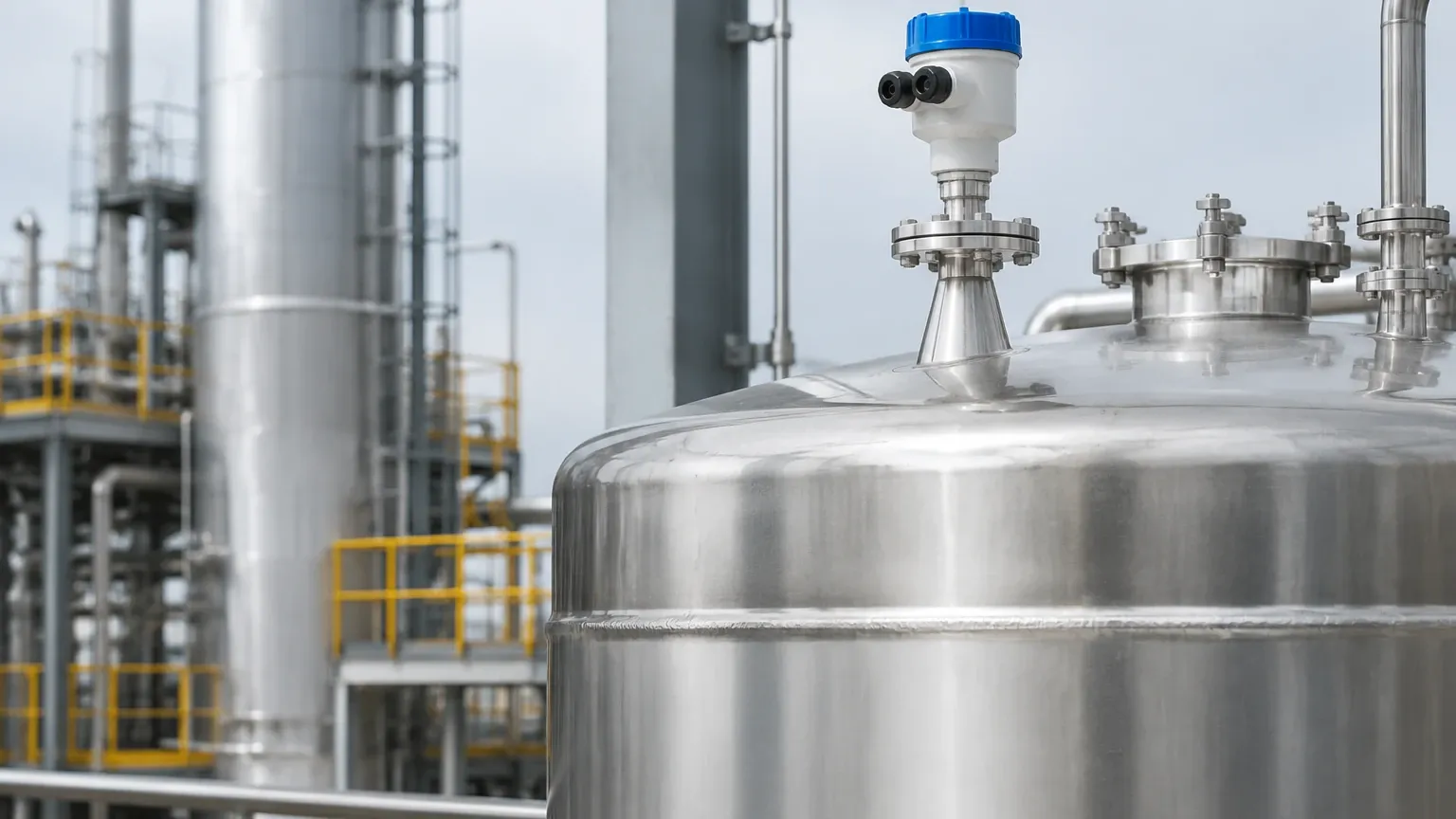
The frequency of the radar signal significantly impacts performance. Higher frequencies (like 80 GHz) allow for smaller antenna sizes and narrower beam angles. A narrow beam is less likely to hit tank walls or internal obstructions, simplifying the installation process in narrow vessels or tanks with complex internals.
Installation Considerations and Best Practices
Even the most advanced radar transmitter will fail if installed incorrectly. Engineers should follow these factual boundaries during the design phase:
1. Avoid the Center: Do not install the transmitter in the exact center of a domed-roof tank, as this can cause multiple reflections that interfere with the signal. Typically, the sensor should be placed at 1/4 to 1/6 of the tank diameter from the wall.
2. Nozzle Height and Diameter: The antenna should ideally extend slightly beyond the mounting nozzle to prevent the nozzle edge from creating a large false echo. If the nozzle is long, a higher frequency radar or a wave-guide may be required.
3. The Dead Zone (Blocking Distance): Every radar has a minimum measurable distance near the antenna (typically 50 mm to 200 mm). Ensure the maximum fill level does not enter this zone, as measurement becomes unreliable.
4. Obstruction Clearance: Ensure the "signal beam" (calculated based on the beam angle) does not intersect with agitators or fill streams. If an agitator is present, the software must be configured to use "False Echo Suppression" while the agitator is running.
Limitations and Application Risks
While versatile, radar technology is not a universal solution. Engineers must be aware of the following limitations:
* Extremely Low Dielectric Materials: Materials with a dielectric constant below 1.4 (like certain liquefied gases) may not reflect enough energy for non-contact radar. In these cases, Guided Wave Radar or a stilling well is necessary.
* Heavy Foam: Dense, thick foam can absorb or scatter the microwave signal, leading to a "loss of echo." While some frequencies penetrate light foam better than others, heavy aqueous foam remains a challenge.
* Vacuum and Pressure: While radar works in a vacuum, the mechanical seal of the transmitter must be rated for the process pressure. High-pressure applications often require specialized glass-sealed feedthroughs.
Frequently Asked Questions (FAQs)
Q: Does the color or transparency of a liquid affect radar measurement?
No. Radar uses electromagnetic waves, not light. The optical properties of the medium (color, clarity, opacity) have no impact on the measurement.
Q: Can radar measure the interface between two liquids?
Yes, but typically only with Guided Wave Radar. If the top layer has a low dielectric constant (e.g., oil) and the bottom layer has a high dielectric constant (e.g., water), the signal will reflect off both surfaces, allowing for interface measurement.
Q: Is radar safe for use in explosive environments?
Yes. Most industrial radar transmitters, such as those manufactured by Welk, are available with ATEX, IECEx, or FM certifications for use in hazardous areas (Ex d or Ex i).
Q: How does dust affect the measurement in solids silos?
High-frequency radar (80 GHz) is particularly effective in dusty environments. Because the wavelength is small, it can penetrate heavy dust clouds that would completely block ultrasonic or optical sensors.
Conclusion
Understanding how does a radar level transmitter work is the first step in optimizing process automation. By leveraging the speed of light and advanced signal processing, these instruments provide a level of precision and durability that few other technologies can match. Whether managing water treatment facilities, chemical reactors, or large-scale grain silos, selecting the correct frequency and mounting configuration ensures long-term operational success. For specific technical specifications and model comparisons, engineers should consult professional manufacturers to match the instrument's capabilities with their specific process requirements.