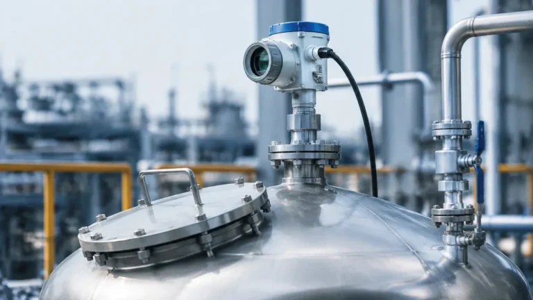
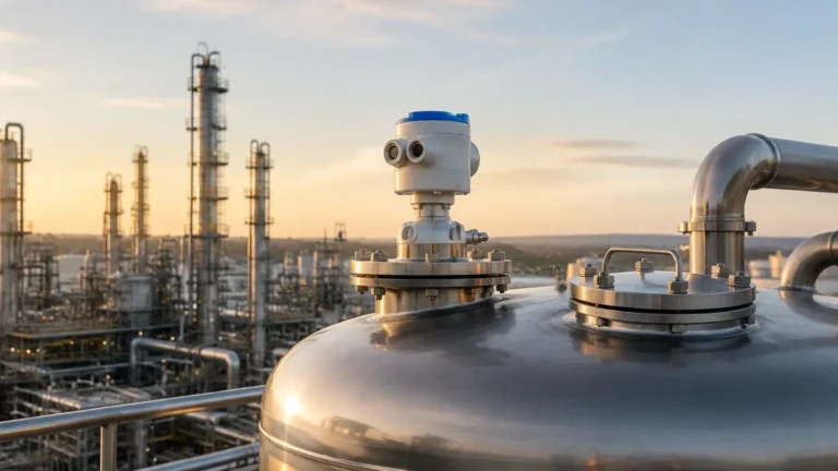
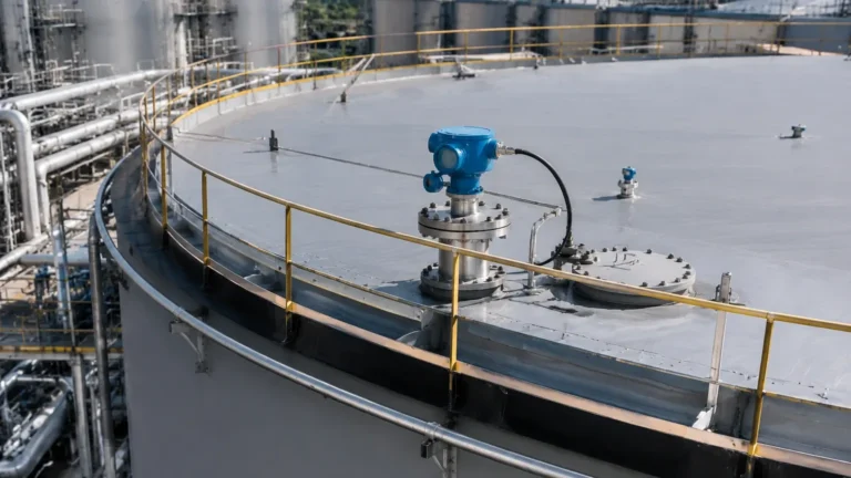
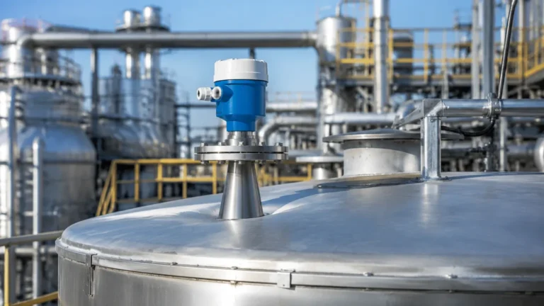
How to Calibrate Radar Level Transmitter
How to Calibrate Radar Level Transmitter: A Technical Engineering Guide
In modern industrial automation, the accuracy of level measurement is fundamental to process safety, inventory management, and operational efficiency. Radar level meters have become the industry standard for non-contact measurement due to their ability to operate under extreme temperatures, high pressures, and varying vapor conditions. However, the reliability of these instruments depends heavily on correct commissioning and periodic calibration.
This guide provides a comprehensive technical overview of how to calibrate radar level transmitter systems, covering the underlying physics of measurement, step-by-step procedures, and the critical installation factors that influence signal integrity.
Understanding Radar Measurement Principles
Before performing a calibration, engineers must understand how Radar Level Meters interact with the process medium. Most industrial radar transmitters utilize one of two primary technologies: Pulse Radar or Frequency Modulated Continuous Wave (FMCW).
Pulse Radar (Time-of-Flight)
Pulse radar transmitters emit high-frequency microwave bursts toward the product surface. The instrument measures the time it takes for the pulse to travel to the surface and return to the antenna. Since the speed of light is constant, the distance is calculated as:
Distance = (Speed of Light × Travel Time) / 2
FMCW Radar
FMCW (Frequency Modulated Continuous Wave) radar transmits a continuous signal with a constantly changing frequency. The reflected signal is compared to the transmitted signal at that moment. The frequency difference between the two is directly proportional to the distance. FMCW is generally preferred for high-precision applications and low-dielectric materials because it provides a better signal-to-noise ratio.
Regardless of the technology, the transmitter converts the measured distance into a level reading based on the user-defined tank height (Zero point) and the desired measurement range (Span).
—
Pre-Calibration Requirements and Safety
Calibration should always be performed by qualified personnel using calibrated master instruments. Before beginning, ensure the following:
1. Safety Documentation: Obtain necessary work permits, especially if the tank contains hazardous chemicals or is under pressure. Check the instrument's ATEX/IECEx rating if working in explosive atmospheres.
2. Tools: A HART (Highway Addressable Remote Transducer) communicator, a PC with manufacturer-specific software (such as PACTware or Rosemount Radar Master), and a high-precision digital multimeter (DMM).
3. Process Stability: Ideally, calibration should be performed when the tank level can be varied. If the tank must remain in service, "dry calibration" via software is possible, though less accurate than a full-loop check.
—
Step-by-Step: How to Calibrate Radar Level Transmitter
Calibration typically involves setting the reference points for the 4-20mA analog output and mapping the tank's internal environment to eliminate false echoes.
1. Physical Inspection and Cleaning
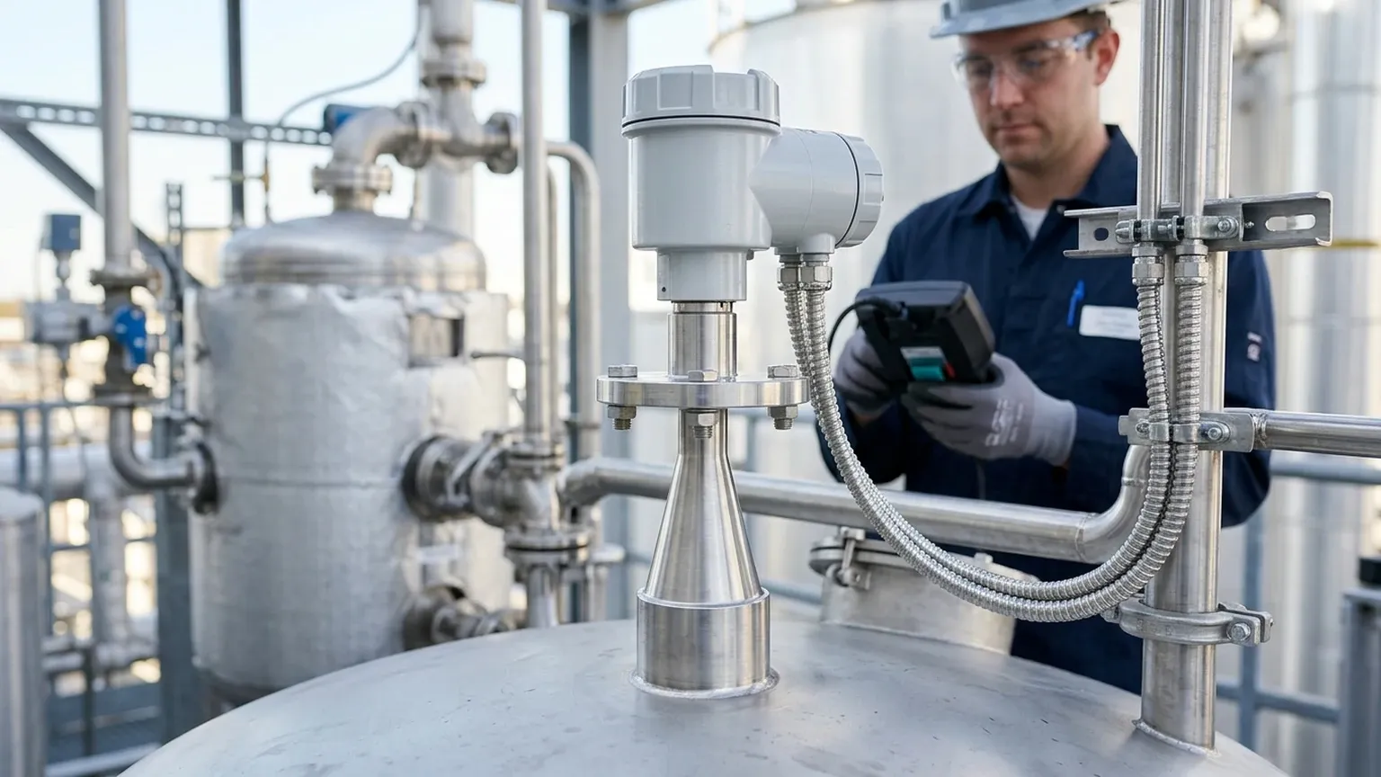
The first step in any calibration is ensuring the hardware is intact. Inspect the antenna (horn, rod, or lens) for any buildup of condensate, dust, or product crystallization. Even the most advanced radar level meters can experience signal attenuation if the emitting face is heavily coated.
2. Establishing the Zero Point (LRV)
The "Zero" point, or Lower Range Value (LRV), usually corresponds to the 4mA output. This is typically the bottom of the tank or the lowest point the process allows.
* Procedure: Measure the distance from the transmitter reference flange to the tank bottom. Enter this value into the transmitter as the "Tank Height" or "Zero Level."
* Verification: With the tank empty, the transmitter should read 0% level and output 4.00mA.
3. Establishing the Span Point (URV)
The "Span," or Upper Range Value (URV), corresponds to the 20mA output. This is the 100% full level.
* Constraint: The 100% point must not enter the transmitter's "Blocking Distance" (Dead Zone). For most 26GHz or 80GHz radars, this is between 50mm and 300mm (approx. 2 to 12 inches) from the antenna.
* Procedure: Determine the maximum safe fill height and enter this as the Span.
4. Dielectric Constant ($ε_r$) Configuration
The reflectivity of a material is determined by its dielectric constant. Water has a high $ε_r$ (~80) and reflects signals strongly. Hydrocarbons like oil or diesel have low $ε_r$ (~2.0), meaning the signal is weaker.
* When calibrating, ensure the correct material type is selected in the software. If the $ε_r$ is very low (below 1.5), a guided wave radar or a high-frequency 80GHz FMCW radar may be required for a stable signal.
5. False Echo Mapping (Envelope Curve)
This is the most critical step in radar calibration. Every tank has internal obstructions—ladders, agitators, heating coils, or inlet pipes—that create "ghost" reflections.
* Procedure: Use the HART communicator or PC software to view the "Echo Curve." While the tank is as empty as possible, perform a "False Echo Suppression" or "Background Mapping." The transmitter will record all static reflections and ignore them during actual operation, focusing only on the moving level signal.
—
Practical Selection Table for Radar Technologies
Choosing the right instrument simplifies the calibration process. The table below outlines common industrial configurations.
| Application | Recommended Frequency | Typical Range | Key Advantage |
| :— | :— | :— | :— |
| Water/Wastewater | 26 GHz | Up to 30m (98 ft) | Cost-effective, handles condensation well. |
| Corrosive Chemicals | 80 GHz | Up to 120m (393 ft) | Small beam angle avoids nozzle reflections. |
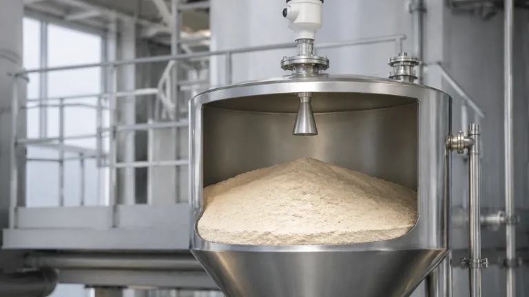
| Solid Powders/Grain | 80 GHz | Up to 100m (328 ft) | Penetrates dust; narrow beam for narrow silos. |
| High-Pressure Steam | Guided Wave Radar | Up to 20m (65 ft) | Signal is guided by a probe, unaffected by vapor. |
| Small Vessels/Tanks | 80 GHz | 0.5m – 10m (1.6 – 32 ft) | Minimal dead zone; high precision in tight spaces. |
—
Installation Considerations for Accurate Calibration
Calibration cannot fix a poorly installed instrument. To ensure the radar level meter performs to its specification, adhere to these engineering constraints:
* Nozzle Geometry: The antenna should ideally extend slightly beyond the mounting nozzle to prevent "ringing" or internal reflections within the nozzle neck.
* Positioning: Never mount the transmitter in the center of a domed tank, as this can concentrate multiple reflections (parabolic effect). Mount it at 1/3 to 1/2 of the tank radius.
* Obstruction Clearance: Ensure the signal beam (which spreads as it travels) does not hit the tank wall or internal pipes. A 10° beam angle will have a diameter of approximately 1.7m at a distance of 10m.
* Inlet Turbulence: Avoid mounting the radar directly above the product inlet. The turbulence and bubbles created by filling will scatter the signal, leading to "Loss of Echo" errors.
—
Limitations and Application Risks
While radar is highly versatile, certain conditions can challenge its accuracy:
1. Heavy Foam: Dense, thick foam (like protein foam) can absorb the microwave signal entirely, preventing a return echo. In these cases, a mechanical level gauge or a guided wave radar might be more appropriate.
2. Extremely Low Dielectrics: Materials with $ε_r < 1.4$ (e.g., liquid nitrogen or certain liquefied gases) may not reflect enough energy for a standard non-contact radar.
3. Vacuum Conditions: While radar works in a vacuum, the flange seals must be specifically rated for vacuum service to prevent air ingress or sensor damage.
—
Frequently Asked Questions (FAQs)
Q: How often should I calibrate my radar level transmitter?
A: For standard inventory applications, an annual verification is sufficient. For safety-instrumented systems (SIS) or high-accuracy custody transfer, semi-annual calibration or proof testing is recommended.
Q: Can I calibrate the radar while the agitator is running?
A: It is best to perform the initial "False Echo Mapping" with the agitator off. Once the map is saved, you can turn the agitator on. Modern radars have algorithms to filter out the intermittent signals caused by moving blades.
Q: What is the difference between "Dry" and "Wet" calibration?
A: Dry calibration involves entering tank dimensions and parameters via software without changing the liquid level. Wet calibration involves physically moving the level to at least two points (e.g., 20% and 80%) to verify the transmitter's response against a manual measurement.
Q: Why does my radar read "Full" when the tank is empty?
A: This is often caused by a strong reflection from a nozzle or an internal obstruction near the top of the tank that hasn't been mapped out. Performing a new background suppression scan usually resolves this.
—
Conclusion
Knowing how to calibrate radar level transmitter hardware is a vital skill for process engineers and maintenance technicians. By understanding the relationship between the microwave signal and the tank environment, and by utilizing modern HART-based mapping tools, users can ensure their Radar Level Meters provide years of maintenance-free service. Always prioritize physical installation quality and correct dielectric settings to achieve the highest possible measurement confidence in industrial B2B environments.