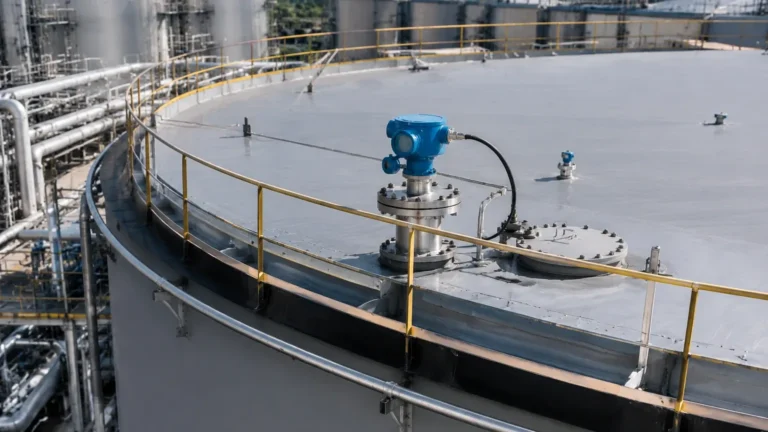
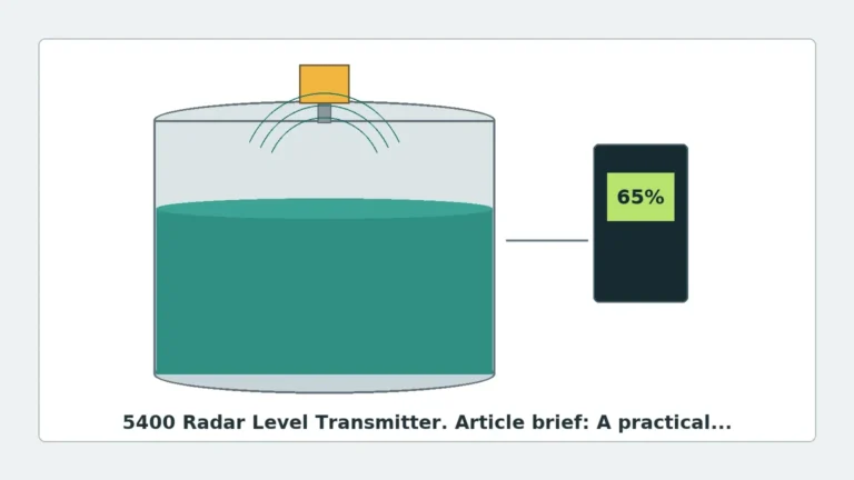
Krohne Radar Level Transmitter
Krohne Radar Level Transmitter: A Technical Engineering Guide to Industrial Application
In the landscape of industrial process automation, precise level measurement is critical for inventory management, safety, and operational efficiency. Among the various technologies available, the krohne radar level transmitter stands out as a benchmark for non-contact measurement in demanding environments. This guide explores the engineering principles, selection criteria, and installation requirements for implementing radar technology in industrial settings.
Understanding Radar Level Measurement Principles
Before selecting a specific instrument, it is essential to understand the physics of radar measurement. Radar level meters operate on the "Time of Flight" (ToF) principle. The device emits electromagnetic waves toward the surface of the medium. These waves are reflected back to the sensor, and the distance is calculated based on the time taken for the signal to travel the round trip.
FMCW vs. Pulsed Radar
While some manufacturers utilize pulsed radar, Krohne is a pioneer in Frequency Modulated Continuous Wave (FMCW) technology.
1. Pulsed Radar: This method sends a short microwave pulse and measures the time it takes to return. While energy-efficient, it can struggle with signal-to-noise ratios in turbulent or complex environments.
2. FMCW Radar: The krohne radar level transmitter typically employs FMCW. In this mode, the transmitter emits a high-frequency signal whose frequency varies linearly over time (a frequency sweep). The reflected signal is compared to the emitted signal at that moment. The frequency difference between the two is directly proportional to the distance. FMCW provides superior accuracy and better signal processing, making it ideal for measuring liquids and solids even in the presence of foam or agitation.
The Role of the Dielectric Constant (εr)
The reflection of the radar signal depends on the dielectric constant of the medium. Materials with high dielectric constants (like water, εr ≈ 80) reflect signals strongly. Materials with low dielectric constants (like hydrocarbons or dry powders, εr < 2) reflect very little energy, requiring highly sensitive Radar Level Meters and specialized antenna designs to ensure reliable tracking.
The Krohne OPTIWAVE Series: Technology Overview
Krohne’s radar portfolio, primarily under the OPTIWAVE brand, is categorized by frequency and application. Selecting the right frequency is the most critical decision in the engineering phase.
* 80 GHz Radar: These transmitters use a very narrow beam angle, which is ideal for small tanks with internal obstructions or for measuring solids where the surface may be uneven. They are less affected by nozzle interference.
* 24 GHz Radar: A versatile frequency used for most liquid applications. It balances beam width and signal strength, performing well in larger tanks or where some foam may be present.
* 6 GHz Radar: Used primarily in applications with heavy agitation or extreme steam, where higher frequencies might suffer from signal scattering.
Selection Criteria for Industrial Applications
Choosing a krohne radar level transmitter requires a detailed analysis of the process conditions. The following table provides a generalized selection framework for different industrial scenarios.
Table 1: Radar Selection Framework
| Process Condition | Recommended Frequency | Antenna Type | Engineering Consideration |
| :— | :— | :— | :— |
| Corrosive Liquids | 80 GHz | PTFE Drop Antenna | Minimize exposed metal parts; ensure chemical compatibility. |
| Large Grain Solids | 24 GHz / 80 GHz | Lens Antenna | Use aiming kits to account for the angle of repose. |
| Agitated Tanks | 6 GHz / 24 GHz | Horn Antenna | Position away from the agitator blades to avoid false reflections. |
| High Pressure/Temp | 24 GHz | Metallic Horn | Use specialized seals (e.g., Kalrez) and thermal spacers. |
| Small Vessels | 80 GHz | Small Threaded Lens | Narrow beam avoids nozzle walls and internal pipes. |
Installation Guidelines and Constraints
Correct installation is the difference between a reliable measurement and constant maintenance issues. Engineers must adhere to strict geometric constraints when mounting a krohne radar level transmitter.
1. Nozzle Geometry
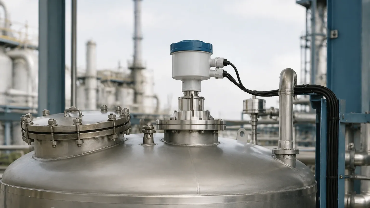
The nozzle height should be kept as short as possible. If the nozzle is too long or narrow, the radar signal may reflect off the internal walls of the nozzle before reaching the medium, creating a "dead zone" or false peak. For 80 GHz units, this is less of a concern, but for 24 GHz units, the antenna should ideally extend slightly below the nozzle bottom.
2. Distance from Tank Walls
Radar waves spread out in a cone. If the transmitter is mounted too close to the tank wall, the signal will reflect off the wall (and any weld seams or ladders), causing interference. A general rule of thumb is to mount the device at least 200 mm (approx. 8 inches) from the wall, or at 1/4 of the tank diameter for smaller vessels.
3. Avoiding Obstructions
Internal structures like heating coils, ladders, and agitators act as reflectors. While modern software can "map out" these static reflections, it is best practice to install the transmitter in a location with a clear line of sight to the product surface. If an agitator is present, the software must be configured to filter out intermittent reflections.
4. Mounting Orientation
The transmitter should be mounted vertically (perpendicular to the liquid surface). For solids, an aiming flange is often used to tilt the transmitter so that the beam is perpendicular to the slope of the material, maximizing the returned signal strength.
Operational Limitations and Risks
While Radar Level Meters are highly robust, they are not universal solutions. Engineers must be aware of the following limitations:
* Heavy Foam: Extremely thick, dense foam can absorb the radar signal entirely, leading to a "Loss of Echo" (LoE) error. In such cases, a guided wave radar (GWR) or a lower frequency (6 GHz) may be required.
* Vacuum Conditions: While radar works in a vacuum, the seals and process connections must be rated for it. Rapid pressure changes can also affect the mechanical integrity of the antenna housing.
* Condensation and Buildup: While many Krohne antennas feature a "drop" design to shed condensation, heavy buildup of viscous or crystallizing media on the antenna lens will eventually attenuate the signal.
Technical Specifications for International Procurement
When specifying a krohne radar level transmitter for a project, international buyers should confirm the following technical parameters to ensure site compatibility:
1. Process Connection: Flange standards (ANSI, DIN, JIS) and sizes (DN50 to DN200 or 2" to 8").
2. Output Protocol: Most units support 4-20 mA HART, but PROFIBUS PA or Foundation Fieldbus may be required for specific automation architectures.
3. Hazardous Area Ratings: Ensure the device carries the necessary certifications (ATEX, IECEx, FM, or CSA) for the specific zone (e.g., Zone 0/1).
4. Housing Material: Choose between aluminum (standard) or stainless steel (for offshore or food-grade environments).
Frequently Asked Questions (FAQ)
Q: Can a radar transmitter measure through a plastic tank roof?
A: Yes, certain radar frequencies can penetrate plastic or fiberglass (GRP) roofs, allowing for non-invasive measurement. This requires the tank material to be non-conductive and the transmitter to be mounted correctly above the tank.
Q: What is the maintenance cycle for a krohne radar level transmitter?
A: Because there are no moving parts, these devices require very little maintenance. An annual visual inspection of the antenna for buildup and a loop check of the electronics is typically sufficient.
Q: How does temperature affect the accuracy of radar?
A: Unlike ultrasonic sensors, radar waves are electromagnetic and do not require a medium (like air) to travel. Therefore, changes in air temperature, pressure, or vapor composition have a negligible effect on the speed of the signal and the resulting accuracy.
Q: Is 80 GHz always better than 24 GHz?
A: Not necessarily. While 80 GHz offers a narrower beam and better resolution, 24 GHz is often more robust in the presence of heavy steam or certain types of foam. The choice depends entirely on the specific application physics.
Conclusion
The implementation of a krohne radar level transmitter provides industrial facilities with a high-precision, low-maintenance solution for level monitoring. By understanding the nuances of FMCW technology and adhering to strict installation guidelines regarding nozzle geometry and dielectric properties, engineers can ensure long-term reliability. For a broader look at available hardware configurations and technical support for your specific application, you may Review product options and application support to find the optimal fit for your process requirements.