Parts of Radar Level Transmitter
Parts of Radar Level Transmitter: A Technical Guide for Industrial Engineering
In the landscape of modern industrial automation, the precision of level measurement is a critical factor in ensuring process safety, inventory accuracy, and operational efficiency. Among the various technologies available, Radar Level Meters have emerged as a gold standard for non-contact measurement in challenging environments. Understanding the specific parts of radar level transmitter systems is essential for engineers and procurement specialists to select the right equipment for applications ranging from wastewater treatment to high-pressure chemical reactors.
This guide provides a comprehensive technical breakdown of radar level transmitter components, their operating principles, and the engineering considerations required for successful integration into industrial processes.
1. Measurement Principles of Radar Technology
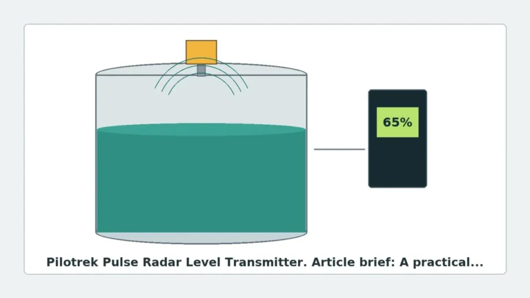
Before examining the individual components, it is necessary to understand how these devices function. Radar level transmitters utilize electromagnetic waves, typically in the microwave frequency range (6GHz to 80GHz), to detect the distance to a product surface.
Time of Flight (ToF)
The most common principle is Time of Flight. The transmitter emits a high-frequency microwave pulse that travels at the speed of light. When the pulse hits the surface of the medium (liquid or solid), a portion of the energy is reflected back to the antenna. The device measures the time interval between emission and reception. The distance ($D$) is calculated using the formula:
$$D = \frac{c \times t}{2}$$
Where $c$ is the speed of light and $t$ is the measured time.
Frequency Modulated Continuous Wave (FMCW)
Advanced high-frequency radar units often use FMCW. Instead of a single pulse, the transmitter emits a continuous signal with a constantly changing frequency. The difference in frequency between the emitted signal and the reflected signal is proportional to the distance. This method offers higher accuracy and better signal-to-noise ratios, particularly in 80GHz systems.
2. Core Parts of Radar Level Transmitter
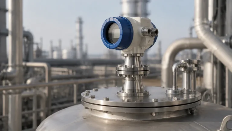
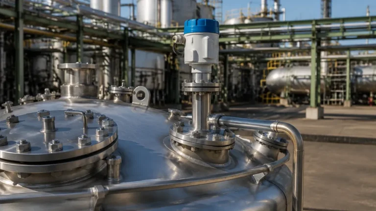
A radar level transmitter is a sophisticated assembly of electronic and mechanical components designed to withstand harsh industrial conditions. The following are the primary parts of radar level transmitter units:
2.1 The Transmitter Housing (The Head)
The housing contains the "brains" of the instrument. It protects the sensitive electronics from environmental factors such as moisture, dust, and corrosive vapors.
* Materials: Typically constructed from Die-cast Aluminum (epoxy coated) or Stainless Steel (316L) for hygienic or highly corrosive environments.
* Electronics Module: Includes the microwave generator, signal processor, and converter. Modern units utilize Digital Signal Processing (DSP) to filter out "false echoes" caused by tank internal structures like agitators or ladders.
* Display and Interface: Most industrial units feature an integrated LCD for local configuration and real-time level monitoring. Communication protocols like 4-20mA HART, Modbus RS485, or Profibus are standard.
* Ingress Protection: High-quality housings are rated at IP67 or IP68 to ensure longevity in outdoor or wash-down areas.
1
2.2 The Antenna (The Transceiver)
The antenna is perhaps the most critical of the parts of radar level transmitter because it determines the beam angle and signal strength.
* Horn Antenna: The most common type for liquid measurement. It is robust and suitable for a wide range of temperatures and pressures.
* Lens/Drop Antenna: Often made of PTFE or PFA, these are used in highly corrosive environments or applications where condensation and buildup are concerns. The curved surface allows droplets to run off, preventing signal attenuation.
* Rod Antenna: Typically used in small-diameter nozzles or for measuring corrosive liquids in small tanks.
* Parabolic Antenna: Used for long-range measurements (up to 70-100 meters) or for materials with low dielectric constants, as it focuses the beam very tightly.
2.3 The Process Connection
This component secures the transmitter to the vessel. The choice of connection depends on the pressure and temperature of the process.
* Threaded Connections: Common in smaller tanks or plastic vessels (e.g., G1½” or 2” NPT).
* Flanged Connections: Used in high-pressure or high-temperature industrial vessels. Standard sizes include DN50 to DN200 (ANSI or DIN standards).
* Hygienic Connections: For food and pharmaceutical industries, Tri-Clamp or aseptic connections are used to ensure no bacterial growth in dead spaces.
2.4 The Waveguide and Seals
In high-temperature or high-pressure applications, the internal waveguide must be protected.
* Pressure Seals: Often made of Viton, Kalrez, or Graphite, these prevent process media from entering the housing.
* Thermal Isolators: Extensions that move the electronics further away from the hot process connection, allowing the transmitter to operate even when the vessel temperature exceeds 200°C.
3. Technical Selection Criteria
When selecting the specific parts of radar level transmitter for your facility, several engineering variables must be considered:
| Feature | 26GHz Radar | 80GHz Radar |
| :— | :— | :— |
| Beam Angle | Wider (approx. 8° – 20°) | Narrow (approx. 3° – 6°) |
| Accuracy | ±3mm to ±5mm | ±1mm |
| Max Range | Up to 30m – 70m | Up to 120m |
| Dust/Steam Resistance | Moderate | High (Better penetration) |
| Application | Large tanks, liquids | Narrow silos, solids, agitators |
Dielectric Constant ($\\epsilon_r$)
The reflectivity of the microwave signal depends on the dielectric constant of the medium.
* High $\\epsilon_r$ (Water, Acids): Reflect signals strongly; easy to measure.
* Low $\\epsilon_r$ (Oils, Solvents, Hydrocarbons): Reflect signals weakly; require high-sensitivity radar or Guided Wave Radar (GWR).
4. Installation Considerations and Constraints
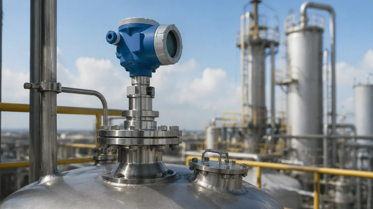
The performance of the radar level transmitter is heavily dependent on proper installation. Even the highest quality parts will fail to provide accurate data if positioned incorrectly.
1. Nozzle Height and Diameter: The antenna should ideally extend slightly beyond the bottom of the mounting nozzle to prevent internal reflections. If the nozzle is long, a waveguide extension may be required.
2. Obstruction Clearance: The radar beam spreads as it travels. Engineers must ensure the "beam cone" does not intersect with pipes, heating coils, or agitator blades.
3. Blocking Distance (Dead Band): Every radar has a minimum distance (usually 100mm to 500mm) from the antenna tip where measurement is not possible. The transmitter must be mounted high enough to account for the maximum fill level.
4. Mounting Position: Avoid mounting the transmitter in the center of a dome-roof tank, as this can cause multiple reflections that confuse the signal processor. Ideally, mount it at 1/3 of the tank radius.
5. Limitations and Application Risks
While radar is highly versatile, it is not a universal solution. Certain conditions can interfere with the microwave signal:
* Heavy Foam: Dense, thick foam can absorb the radar signal entirely, leading to a "loss of echo." In such cases, a contact-based solution like a magnetic level gauge or a displacement transmitter might be preferred.
* Turbulence: Extreme surface agitation can scatter the signal. This is often mitigated through software filtering or by using a stilling well (a bypass pipe that provides a calm surface).
* Vacuum and Pressure: While microwaves travel through a vacuum, the physical parts of radar level transmitter—specifically the seals and flanges—must be rated for the specific pressure (e.g., PN16, PN40).
6. Maintenance and Troubleshooting
One of the primary benefits of non-contact radar is the low maintenance requirement. However, periodic checks are recommended:
* Antenna Buildup: In sticky or crystallizing media, check the antenna for coating. Even though many modern radars can "see through" thin layers of buildup, heavy accumulation will eventually degrade the signal.
* Cable Glands: Ensure cable entries are tight to prevent moisture ingress into the housing, which is the leading cause of electronic failure.
* Signal Diagnostics: Use the HART interface to check the "Echo Curve." A healthy signal should show a clear, sharp peak at the product surface with minimal noise peaks from tank internals.
7. Frequently Asked Questions (FAQ)
Q: Can radar level transmitters measure solids?
A: Yes. However, solids like grain or plastic pellets often have an angled surface (angle of repose) and lower dielectric constants. High-frequency 80GHz radars with narrow beam angles are generally recommended for solids to ensure a reliable return signal.
Q: What is the difference between Guided Wave Radar and Non-contact Radar?
A: Guided Wave Radar (GWR) uses a physical probe (cable or rod) to guide the microwave signal to the surface. It is better for low dielectric fluids and applications with heavy foam or turbulence. Non-contact radar (as discussed here) is preferred for corrosive, hygienic, or high-temperature applications where touching the media is undesirable.
Q: How does temperature affect the measurement?
A: Unlike ultrasonic sensors, radar signals are electromagnetic and are not affected by air temperature, pressure, or vapor composition. However, the physical components (electronics and seals) have specific temperature limits that must be respected.
Conclusion
Selecting the appropriate parts of radar level transmitter requires a balanced understanding of the process environment and the mechanical capabilities of the instrument. From the material of the housing to the geometry of the antenna, each component plays a vital role in ensuring long-term reliability. For industrial operators looking to upgrade their level measurement systems, focusing on high-frequency 80GHz technology and robust antenna materials like PTFE will typically yield the best return on investment.
For more detailed technical specifications and to explore various configurations, engineers are encouraged to Review product options and application support to find the ideal solution for their specific industrial requirements.