Radar Level Transmitter Dielectric Constant
Radar Level Transmitter Dielectric Constant: An Engineering Guide to Selection and Application
In the field of industrial process control, accurate level measurement is essential for safety, inventory management, and process efficiency. Among the various technologies available, Radar Level Meters have become the industry standard due to their non-contact nature and reliability in harsh environments. However, the performance of these instruments is fundamentally governed by the physical properties of the medium being measured—most notably the dielectric constant.
Understanding the radar level transmitter dielectric constant relationship is critical for engineers and procurement specialists. This guide explores the principles of radar reflection, how dielectric properties influence instrument selection, and the practical considerations required to ensure high-accuracy measurement in diverse industrial applications.
The Physics of Radar Reflection
Radar level transmitters operate on the Time-of-Flight (ToF) principle. The device emits high-frequency electromagnetic waves (microwaves) toward the surface of the product. These waves travel at the speed of light. When they encounter the surface of the medium, a portion of the electromagnetic energy is reflected back to the sensor’s antenna. The transmitter calculates the distance based on the time interval between emission and reception.
The Role of the Dielectric Constant ($ε_r$)
The dielectric constant, or relative permittivity ($ε_r$), is a dimensionless measure of a material's ability to store electrical energy in an electric field. In the context of radar measurement, it determines how much of the radar signal is reflected at the interface between the upper medium (usually air or nitrogen, with $ε_r ≈ 1$) and the process material.
The reflection coefficient ($R$)—the ratio of the reflected signal amplitude to the incident signal amplitude—is calculated using the following simplified formula for a perpendicular wave:
$$R = \frac{\sqrt{ε_r} – 1}{\sqrt{ε_r} + 1}$$
From this relationship, we can derive several key engineering conclusions:
- High Dielectric Materials: Materials with high $ε_r$ (such as water, $ε_r ≈ 80$) reflect a large percentage of the signal, making them very easy to measure even with small antennas or at long distances.
- Low Dielectric Materials: Materials with low $ε_r$ (such as hydrocarbons, solvents, or dry solids) reflect very little energy. For example, oil with an $ε_r$ of 2.0 reflects only about 3% of the signal energy. The remaining energy penetrates the material.
- Signal Loss: If the dielectric constant is too low (typically below 1.4 for non-contact radar), the reflection may be too weak for the transmitter to distinguish from background noise, leading to signal loss.
Categorizing Materials by Dielectric Constant
To simplify instrument selection, industrial materials are generally categorized into four groups based on their dielectric properties:
| Category | Dielectric Constant ($ε_r$) | Typical Materials | Measurement Difficulty |
| :— | :— | :— | :— |
| A (Highly Reflective) | > 10 | Water-based liquids, acids, alkalis, slurries | Very Low |
| B (Moderately Reflective) | 4 to 10 | Concentrated acids, alcohols, moist solids | Low |
| C (Weakly Reflective) | 1.9 to 4 | Diesel, oils, plastic pellets, sulfur | Moderate |
| D (Transparent) | 1.4 to 1.9 | Liquefied gases (LPG), hexane, dry powders | High |
Technology Selection: Non-Contact vs. Guided Wave Radar
When dealing with varying radar level transmitter dielectric constant values, engineers must choose between two primary radar architectures: Non-contact (Free-space) and Guided Wave Radar (GWR).
1. Non-Contact Radar (FMCW and Pulse)
Non-contact Radar Level Meters emit waves through the air. They are ideal for corrosive or hygienic applications where the sensor should not touch the medium.
- High-Frequency (80GHz): Modern 80GHz transmitters offer a narrow beam angle and high sensitivity, allowing them to measure lower $ε_r$ materials more effectively than older 6GHz or 26GHz models.
- Antenna Size: For low $ε_r$ liquids, a larger horn antenna or a parabolic antenna is often required to focus the signal and capture enough reflected energy.
2. Guided Wave Radar (GWR)
GWR uses a physical probe (rod or cable) to guide the microwave signal directly to the surface.
- Energy Concentration: Because the signal is confined to the probe, there is significantly less signal attenuation compared to free-space radar.
- Low $ε_r$ Capability: GWR is the preferred choice for materials with extremely low dielectric constants ($ε_r < 1.6$). It is also the only reliable method for interface measurement (e.g., measuring the level of water beneath a layer of oil).
Critical Selection Criteria for Engineers
Choosing the right radar transmitter requires balancing the dielectric properties with the physical environment of the tank. Consider the following factors:
Surface Conditions and Turbulence
A turbulent surface or the presence of foam significantly reduces the effective reflection. If a liquid has a low dielectric constant and is also turbulent, a non-contact radar may fail. In such cases, a GWR with a coaxial probe or a stilling well for non-contact radar is recommended to stabilize the surface and concentrate the signal.
Measuring Range and Sensitivity
As the distance increases, the radar signal spreads and weakens (Inverse Square Law). For a material with $ε_r = 2.0$, a transmitter might have a maximum effective range of 10 meters (32.8 ft), whereas for water ($ε_r = 80$), the same transmitter could reach 30 meters (98.4 ft) or more.
Interface Measurement
In applications where two liquids with different densities and dielectric constants coexist (e.g., oil over water), the radar signal passes through the upper low-$ε_r$ layer and reflects off the lower high-$ε_r$ layer. For this to work, the upper layer must have a dielectric constant at least 10 units lower than the bottom layer, and the upper layer must be non-conductive.
Installation Considerations and Limitations
Proper installation is as important as technology selection when managing dielectric-related challenges.
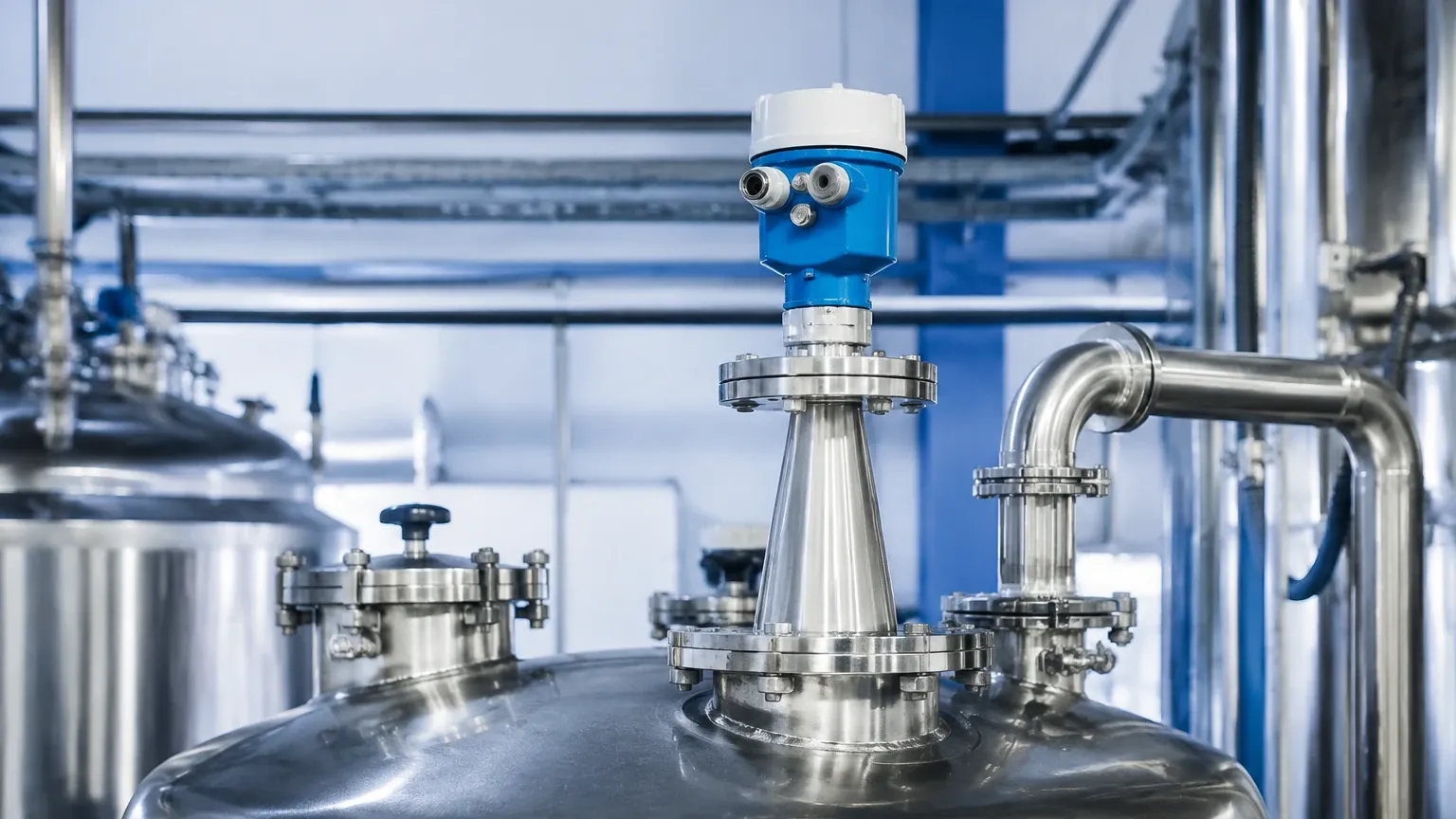
1. Nozzle Geometry: For low dielectric materials, avoid long or narrow mounting nozzles. Nozzles create internal reflections (ringing) that can mask the weak return signal from a low-$ε_r$ product. If a long nozzle is unavoidable, an 80GHz transmitter with a lens antenna is often the best solution.
2. Obstructions: Internal tank structures like ladders, agitators, or heating coils create "false echoes." While software can map these out, a low $ε_r$ product reflection might be weaker than the reflection from a steel pipe, making signal processing difficult.
3. Bottom Reflections: In tanks containing low $ε_r$ liquids, the radar signal may pass through the liquid and reflect off the tank bottom. This can cause the transmitter to report an incorrect level or "lock" onto the bottom signal. Advanced transmitters use "Bottom Echo Tracking" to compensate for this effect.
Application Risks and Mitigation
| Risk Factor | Impact on Measurement | Mitigation Strategy |
| :— | :— | :— |
| Condensation | Attenuates signal, especially on 80GHz lens antennas. | Use an antenna with a PTFE dropper or integrated air purge. |
| Heavy Foam | Absorbs or scatters radar pulses. | Use GWR or lower frequency (6GHz) non-contact radar with a large horn. |
| Vapor/Gas Layers | High-pressure vapor can change the speed of light, affecting accuracy. | Use a GWR with a reference reflection (End-of-Probe) compensation. |
| Dust (Solids) | Scatters signal and reduces return energy. | Use high-frequency (80GHz) radar with high sensitivity and dust-purging ports. |
Buyer’s Checklist: What to Confirm Before Ordering
When consulting with a manufacturer like Welk for a radar level solution, international buyers should provide the following technical data to ensure the equipment matches the application's dielectric requirements:
1. Material Name and $ε_r$: If the dielectric constant is unknown, provide the chemical composition and temperature.
2. Process Temperature and Pressure: Dielectric constants can change with temperature, and high pressure may require specialized seal materials.
3. Tank Dimensions: Height, diameter, and the presence of internal obstructions.
4. Mounting Connection: Flange size and nozzle height.
5. Surface State: Is there agitation, foam, or steam?
Frequently Asked Questions (FAQ)
Q: Can I use a radar level meter if I don't know the dielectric constant?
A: Yes, most modern transmitters have auto-gain control and can detect a wide range of materials. However, for materials with $ε_r < 2.0$, knowing the value is essential to ensure the antenna and frequency selected provide enough signal margin.
Q: Does the dielectric constant of a material change?
A: Yes. Temperature is the primary driver. For most liquids, the dielectric constant decreases as temperature increases. In solids, moisture content significantly increases the dielectric constant.
Q: Why is 80GHz better for low dielectric materials?
A: 80GHz radar has a much higher dynamic range and a narrower beam (as small as 3°). This focuses the energy into a smaller area, resulting in a stronger return signal from even weakly reflective surfaces.
Q: How does a stilling well help with low dielectric liquids?
A: A stilling well acts like a coaxial probe for non-contact radar. It prevents the signal from spreading, eliminates surface turbulence, and ensures that even a 3% reflection is captured by the antenna without interference from tank walls.
Conclusion
The radar level transmitter dielectric constant is the most influential factor in determining the success of a radar-based level measurement system. By understanding the relationship between $ε_r$ and signal reflection, and by selecting the appropriate frequency and mounting configuration, engineers can achieve highly accurate and maintenance-free level monitoring. For complex applications involving low-dielectric hydrocarbons or interface measurement, consulting with a professional instrumentation manufacturer is recommended to ensure the selected technology meets the specific demands of the process environment.
Download Radar Level Transmitter Dielectric Constant as a PDF