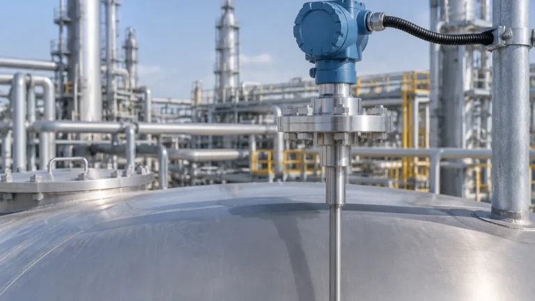
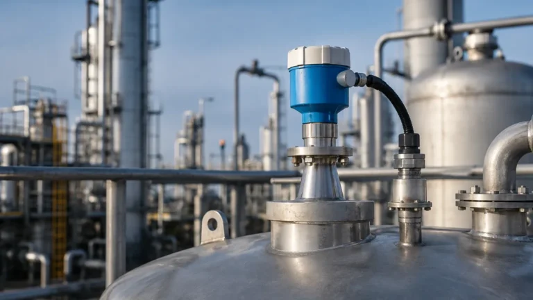
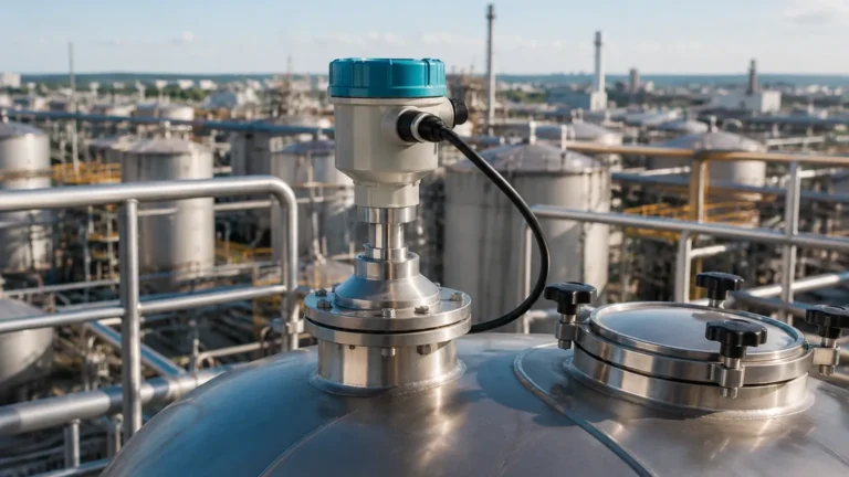
Radar Level Transmitter Vega
Engineering Guide to Radar Level Measurement: Understanding the Radar Level Transmitter Vega and Industrial Standards
In the landscape of industrial automation, precise level measurement is a cornerstone of process safety, inventory management, and operational efficiency. Among the various technologies available, non-contact radar has emerged as the gold standard for challenging environments. When engineers search for a radar level transmitter vega, they are typically looking for high-frequency precision and reliability in demanding applications. This guide explores the underlying principles of Radar Level Meters, selection criteria, and technical considerations essential for integrating these instruments into modern industrial systems.
1. Principles of Radar Level Measurement
Radar level measurement operates on the principle of "Time of Flight" (ToF). The instrument emits high-frequency electromagnetic waves (microwaves) toward the surface of the medium. These waves are reflected by the product surface and received back by the antenna system. Since the speed of light is constant, the time elapsed between emission and reception is directly proportional to the distance between the sensor and the medium.
Pulse Radar vs. FMCW Technology
There are two primary methods used in industrial radar level transmitters:
* Pulse Radar: The sensor emits microwave pulses in short intervals. The electronics measure the time it takes for a single pulse to travel to the surface and back. While energy-efficient, pulse radar can sometimes struggle with signal-to-noise ratios in complex environments.
* FMCW (Frequency Modulated Continuous Wave): This technology emits a continuous signal with a constantly changing frequency. The distance is calculated by measuring the frequency difference between the emitted and the received signal at any given moment. FMCW is widely regarded as superior for high-precision applications, particularly in the 80 GHz frequency range often associated with a high-end radar level transmitter vega.
2. The Impact of Frequency: 6 GHz to 80 GHz
Frequency is perhaps the most critical specification when selecting Radar Level Meters. It determines the beam angle, the size of the antenna, and the ability of the signal to penetrate obstacles or handle surface turbulence.
Low Frequency (approx. 6 GHz)
Lower frequency radars have longer wavelengths. They are less affected by foam, heavy dust, or vapor. However, they require larger antennas to maintain a focus and have a wider beam angle, making them susceptible to interference from internal tank structures like agitators or ladders.
Medium Frequency (approx. 26 GHz)
This is the industrial workhorse frequency. It balances antenna size with signal focusing. It is suitable for a wide range of liquids and some solids, provided the installation environment is relatively clear of obstructions.
High Frequency (80 GHz)
Modern advancements, exemplified by the radar level transmitter vega series, utilize 80 GHz technology. The high frequency allows for a very narrow beam angle (often as small as 3°). This enables the sensor to "see" past narrow nozzles and internal obstructions, providing a much cleaner signal and higher accuracy (often ±1 mm).
3. Technical Selection Criteria
Choosing the right radar instrument requires an analysis of the physical and chemical properties of the process.
Dielectric Constant (εr)
The dielectric constant of the medium determines how much of the radar signal is reflected. Highly conductive materials (like water, εr ≈ 80) reflect signals strongly. Non-conductive materials (like hydrocarbons or dry powders, εr < 2) reflect very little energy. For materials with a dielectric constant below 1.5, specialized high-sensitivity radar or guided wave radar may be required.
Process Conditions
* Temperature and Pressure: Standard sensors typically handle up to 80°C (176°F), but high-temperature versions with ceramic seals can withstand over 400°C (752°F).
* Surface Turbulence: Agitators or boiling liquids create surface ripples that scatter the radar signal. FMCW technology and specialized software algorithms are used to filter this noise.
* Vapor and Condensation: While radar is generally unaffected by vacuum or pressure, heavy condensation on the antenna can attenuate the signal. Selecting an antenna with a PTFE (Teflon) cover can help shed droplets.
4. Selection Table: Application vs. Technology
| Application Type | Recommended Frequency | Key Advantage | Constraints |
| :— | :— | :— | :— |
| Clean Water Storage | 26 GHz / 80 GHz | High accuracy, small footprint | Minimal |
| Chemical Storage (Corrosive) | 80 GHz (PTFE encapsulated) | Chemical resistance, narrow beam | Avoid heavy foaming |
| Cement/Powder Silos | 80 GHz | Penetrates dust, ignores buildup | High dust requires air purging |
| Oil/Hydrocarbon Tanks | 26 GHz | Reliable for low εr liquids | Requires stilling well for very low εr |
| Wastewater (Open Channel) | 80 GHz | Unaffected by ambient weather | Must be mounted perpendicular to flow |
5. Installation Guidelines and Best Practices
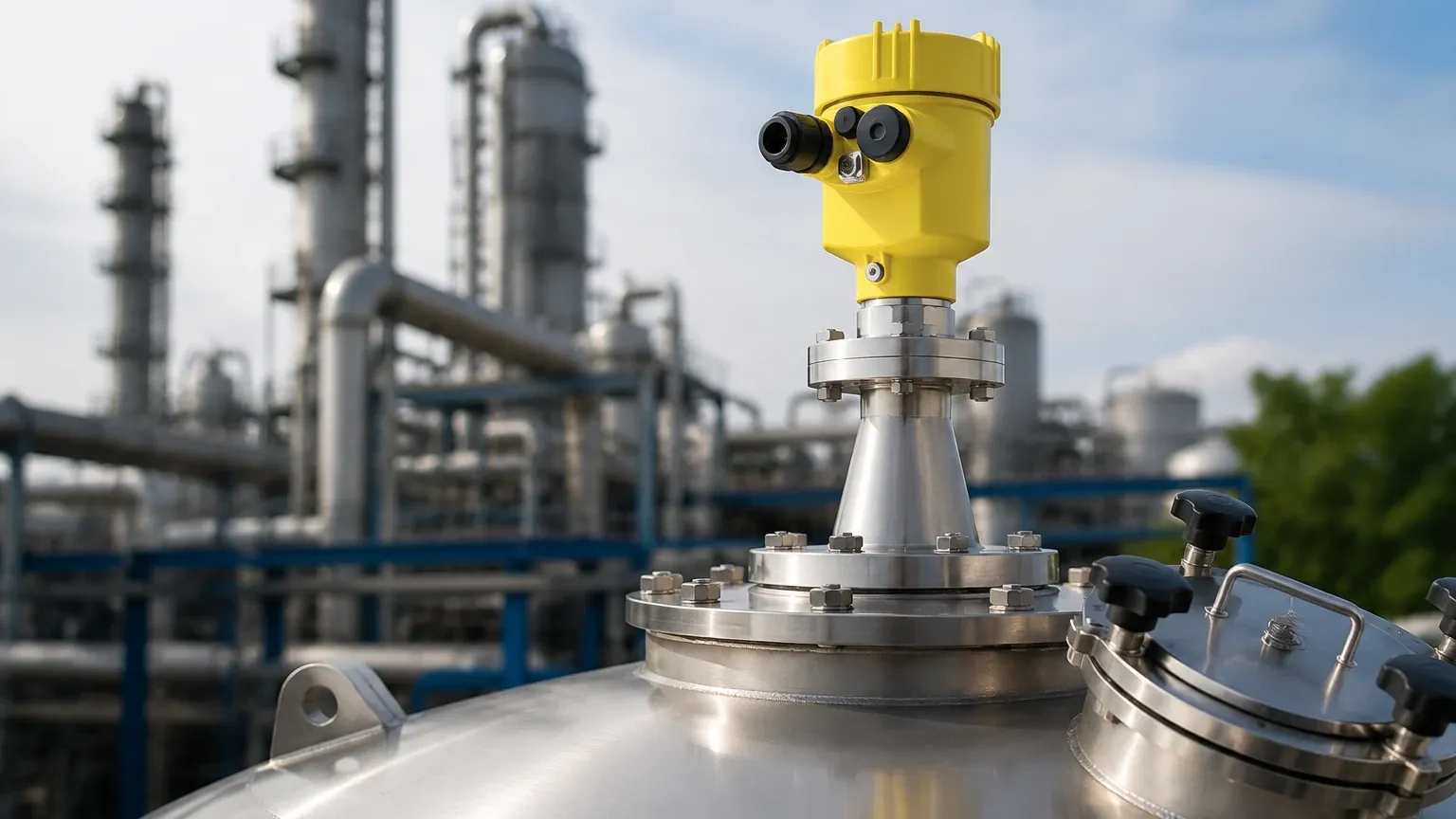
Even the most advanced radar level transmitter vega will fail to perform if installed incorrectly. Engineering teams must adhere to strict mounting geometry.
1. Nozzle Height and Diameter: The antenna should ideally extend slightly beyond the bottom of the mounting nozzle to prevent "ringing" or false reflections from the nozzle edge. If using 80 GHz radar, the narrow beam allows for longer, narrower nozzles than 26 GHz models.
2. Distance from Wall: Sensors should be mounted at a distance from the vessel wall—typically 1/6th of the tank diameter. Mounting too close to the wall can result in signal interference from weld seams or scaling.
3. Avoid the Center: In cylindrical tanks with domed tops, mounting the sensor in the dead center can create a parabolic effect, amplifying unwanted secondary reflections. It also places the sensor directly above the vortex if an agitator is used.
4. Obstruction Clearance: Ensure the signal path is clear of heating coils, ladders, or inflow streams. If obstructions are unavoidable, most modern Radar Level Meters offer "False Signal Suppression" or "Background Masking" to map out these static reflections.
6. Limitations and Application Risks
While radar is versatile, it is not a universal solution. Engineers should be aware of the following limitations:
* Heavy Foam: Dense, thick foam (like shaving cream) can absorb the radar signal entirely, leading to a "Loss of Echo" (LOE). In such cases, hydrostatic pressure or ultrasonic sensors might be considered, though radar remains superior for light, airy foam.
* Extremely Low Dielectric Solids: Very light plastic pellets or dry wood chips may not reflect enough energy for non-contact radar. Guided wave radar (GWR), where the signal travels down a probe, is often the preferred alternative here.
* Vacuum Limitations: While the signal travels through a vacuum, the physical seal of the transmitter must be rated for vacuum service to prevent air ingress or sensor damage.
7. Frequently Asked Questions (FAQ)
Q: Can a radar level transmitter vega measure through a plastic tank roof?
A: Yes. Since plastic (like PE or PP) has a low dielectric constant, microwaves can pass through it. This allows for non-intrusive measurement from outside a plastic IBC or storage tank, provided the roof is not reinforced with metal.
Q: What is the difference between 2-wire and 4-wire radar transmitters?
A: 2-wire (Loop-powered) instruments use the same pair of wires for power and the 4-20mA signal, which simplifies wiring. 4-wire instruments have separate power supplies, allowing for higher power consumption, which is sometimes necessary for older-generation long-range solids radar or units with integrated heaters.
Q: How often does a radar level meter need calibration?
A: Radar is a solid-state technology with no moving parts. Once commissioned and the "zero" and "span" are set, they typically do not drift. Annual verification is recommended for ISO compliance, but physical recalibration is rarely necessary unless process conditions change significantly.
Q: Does the pressure inside the tank affect the accuracy?
A: Unlike ultrasonic sensors, which depend on the speed of sound (which changes with air density/pressure), radar uses electromagnetic waves. Therefore, pressure changes do not affect the travel time or accuracy of the measurement.
Conclusion
The transition toward high-frequency Radar Level Meters has revolutionized how industries monitor their assets. Whether specifying a radar level transmitter vega for a high-precision chemical process or a robust Welk sensor for water treatment, understanding the relationship between frequency, dielectric constants, and vessel geometry is paramount. By following standard engineering practices for installation and selection, facilities can achieve maintenance-free level measurement that stands up to the rigors of modern industrial environments.