Prinsip Kerja Radar Level Transmitter
Prinsip Kerja Radar Level Transmitter: A Technical Engineering Guide
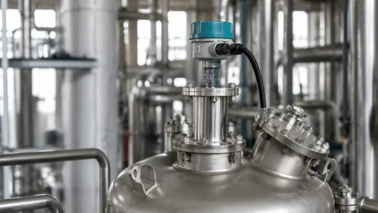
In the landscape of industrial automation, accurate level measurement is critical for inventory management, process safety, and operational efficiency. Among the various technologies available, Radar Level Meters have emerged as the gold standard for non-contact measurement in challenging environments. This article provides a comprehensive technical analysis of the prinsip kerja radar level transmitter (the working principle of radar level transmitters), offering engineering insights into selection, installation, and application constraints.
1. Understanding the Core Measurement Principles
Before diving into specific hardware recommendations, it is essential to understand the physics behind radar-based level detection. Radar (Radio Detection and Ranging) instruments utilize electromagnetic waves, typically in the microwave spectrum, to determine the distance to a product surface. Unlike ultrasonic waves, which are mechanical and require a medium (air) to travel, radar waves are electromagnetic and can operate effectively in a vacuum or through various gas compositions.
There are two primary methods used in industrial radar level measurement: Time of Flight (Pulse Radar) and Frequency Modulated Continuous Wave (FMCW).
Time of Flight (Pulse Radar)
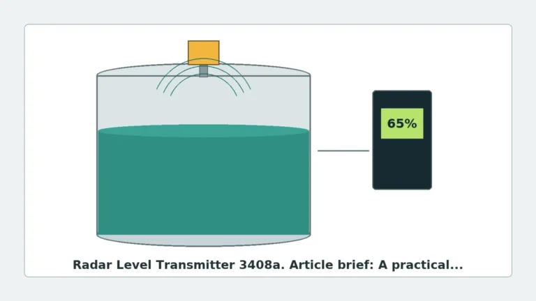
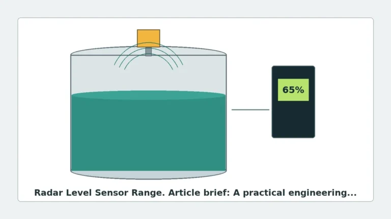
In the Pulse Radar method, the transmitter emits a high-frequency microwave pulse toward the medium. This pulse travels at the speed of light ($c$). When it hits the surface of the material, a portion of the energy is reflected back to the sensor. The instrument measures the time interval ($t$) between the emission and the reception of the echo.
The distance ($D$) is calculated using the formula:
$$D = \frac{c \times t}{2}$$
Since the speed of light is constant, the accuracy depends on the precision of the internal clock and the ability of the signal processor to distinguish the true echo from background noise.
Frequency Modulated Continuous Wave (FMCW)
FMCW radar does not send discrete pulses. Instead, it transmits a continuous signal with a frequency that changes linearly over time (a frequency sweep). When the reflected signal is received, it is compared with the signal being transmitted at that exact moment. The difference in frequency ($\Delta f$) is directly proportional to the travel time, and therefore the distance.
FMCW is generally considered superior for high-precision applications and agitated surfaces because it provides more data points for signal processing, resulting in better noise filtering and accuracy.
2. Prinsip Kerja Radar Level Transmitter: The Technical Process
The prinsip kerja radar level transmitter involves a sophisticated chain of electronic and physical events. To select the right equipment, engineers must understand how the signal interacts with the process environment.
1. Signal Generation: The transmitter's electronic oscillator generates a microwave signal. For industrial applications, these typically fall into C-band (approx. 6 GHz), K-band (26 GHz), or W-band (80 GHz) frequencies.
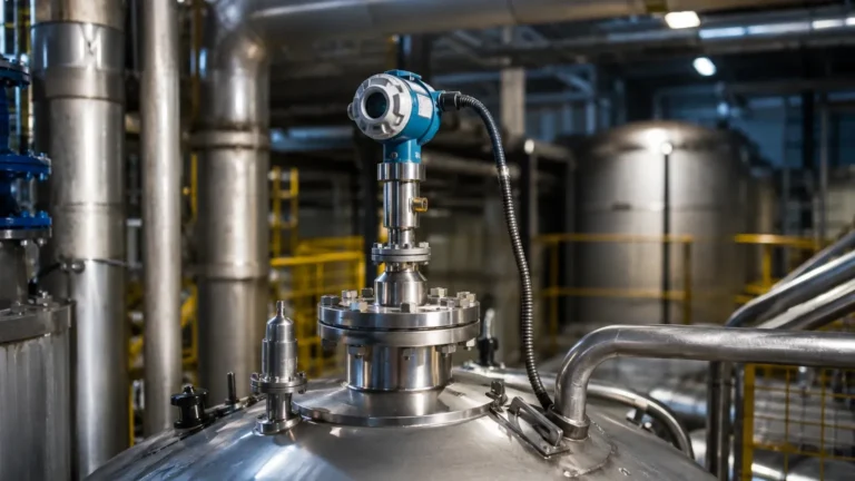
2. Emission via Antenna: The signal is directed through an antenna (horn, lens, or rod) toward the material surface. The antenna design determines the beam angle; a narrower beam focuses more energy on the target and avoids interference from tank walls or internal obstructions.
3. Reflection (The Dielectric Factor): When the microwave hits the medium, the amount of energy reflected depends on the material's dielectric constant ($\epsilon_r$). Materials with high dielectric constants (like water, $\epsilon_r \approx 80$) reflect signals very strongly. Materials with low dielectric constants (like hydrocarbons or dry powders, $\epsilon_r < 2.0$) allow most of the signal to pass through, resulting in a weak echo.
4. Signal Processing: The reflected echo is captured by the antenna and converted into an electrical signal. Advanced algorithms, such as Welk’s proprietary echo-tracking software, filter out "false echoes" caused by agitators, ladders, or weld seams.
5. Output: The calculated level is converted into an industrial output signal, such as 4-20mA (HART), Modbus RTU, or Profibus, for integration into a PLC or DCS.
3. Frequency Selection and Its Impact
Choosing the correct frequency is perhaps the most critical decision in radar level meter specification. The frequency dictates the beam angle and the instrument's ability to handle dust, foam, or turbulence.
| Frequency | Beam Angle | Typical Application | Advantages | Disadvantages |
| :— | :— | :— | :— | :— |
| 6 GHz (C-Band) | Wide (approx. 20-30°) | Large tanks with heavy foam or steam. | Penetrates steam and foam effectively. | Requires large antennas; sensitive to internal tank obstructions. |
| 26 GHz (K-Band) | Medium (approx. 8-12°) | Chemical storage, oil/water separators. | Versatile; smaller antenna size than 6 GHz. | Can be affected by heavy condensation or buildup on the antenna. |
| 80 GHz (W-Band) | Narrow (approx. 3-4°) | Small nozzles, tall silos, solids, agitated liquids. | Extremely precise; ignores tank wall interference; small footprint. | Higher cost; may be attenuated by extremely dense dust or heavy steam. |
4. Installation Considerations and Best Practices
Even the most advanced radar level transmitter will fail if installed incorrectly. Engineers should follow these standard guidelines to ensure reliable performance:
* The 1/6th Rule: Generally, the transmitter should be installed at a distance from the tank wall equal to approximately 1/6th of the tank diameter. This prevents the beam from reflecting off the wall before hitting the product.
* Nozzle Geometry: The antenna should ideally extend past the bottom of the mounting nozzle. If the nozzle is long and narrow, it can create "ringing" or internal reflections that mask the true level signal. For 80 GHz units, this is less of a concern due to the narrow beam.
* Dead Zone (Blocking Distance): Every radar has a minimum measurable distance (typically 50mm to 300mm from the antenna reference point). The maximum fill level must not enter this dead zone, or the signal will be lost or erratic.
* Obstruction Avoidance: Ensure the beam path is clear of heating coils, agitator blades, and ladders. If obstructions are unavoidable, use the "False Echo Suppression" or "Background Subtraction" feature in the software during commissioning.
* Orientation: For solid materials, the angle of repose must be considered. In some cases, a swiveling flange is required to aim the radar beam at the most representative point of the material surface.

5. Limitations and Application Risks
While radar is highly versatile, it is not a universal solution. Engineers must account for the following risks:
1. Low Dielectric Materials: If the product has a dielectric constant below 1.4, standard non-contact radar may struggle to detect the surface. In these cases, a Guided Wave Radar (GWR) or a high-sensitivity 80 GHz FMCW radar is recommended.
2. Heavy Foam: While C-band radar can penetrate some foam, thick, dense foam (like shaving cream consistency) can absorb the radar signal entirely, leading to a "Loss of Echo" (LOE) error.
3. Vacuum and Pressure: While radar works in a vacuum, the mechanical seal of the transmitter must be rated for the process pressure. High-pressure applications often require specialized ceramic or fused glass seals.
4. Antenna Buildup: In sticky or crystallizing applications, material can accumulate on the antenna. While many modern radars have "buildup compensation," excessive coating will eventually attenuate the signal. Air purging systems are a common solution for these environments.
6. Comparison: Radar vs. Other Technologies
| Feature | Radar (Non-Contact) | Ultrasonic | Guided Wave Radar (GWR) |
| :— | :— | :— | :— |
| Medium | Liquids & Solids | Liquids & Solids | Liquids & Solids |
| Vacuum Compatibility | Excellent | None (Requires air) | Excellent |
| Pressure Limits | High (up to 160+ bar) | Low (typically < 3 bar) | High (up to 400 bar) |
| Accuracy | High (±1mm to ±3mm) | Moderate (±0.25% of range) | High (±2mm) |
| Effect of Vapor/Gas | None | Significant | None |
| Contact with Media | No | No | Yes (Probe immersed) |
7. Frequently Asked Questions (FAQ)
Q: Can radar level meters measure the interface between two liquids?
A: Non-contact radar is generally used for the top surface. For interface measurement (e.g., oil over water), Guided Wave Radar (GWR) is typically preferred because the signal can partially pass through the upper layer to reflect off the lower layer.
Q: Does the color or transparency of the liquid affect the measurement?
A: No. Radar is an electromagnetic wave, not an optical one. Color, transparency, and light levels have zero impact on the prinsip kerja radar level transmitter.
Q: How often does a radar level transmitter need calibration?
A: Radar transmitters are solid-state devices with no moving parts. Once calibrated to the tank geometry during commissioning, they rarely drift. Annual verification is recommended for ISO compliance, but recalibration is seldom necessary unless the process medium changes significantly.
Q: Can I use radar in a plastic tank?
A: Yes. In fact, radar signals can often pass through plastic tank roofs. This allows for "through-tank" measurement where the sensor is mounted outside the tank, provided the plastic is not carbon-filled or metallic-lined.
Conclusion
Understanding the prinsip kerja radar level transmitter is the first step toward achieving reliable process control. By matching the frequency, antenna type, and installation method to the specific dielectric and physical properties of the medium, engineers can implement a maintenance-free level solution. Whether dealing with corrosive chemicals, high-temperature bitumen, or fine powders, Radar Level Meters provide the precision and durability required for modern industrial automation.
For technical assistance in selecting the correct model for your specific application, consult with a qualified instrumentation engineer to review tank drawings and material safety data sheets (MSDS).