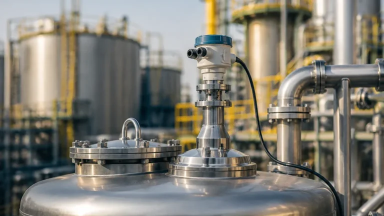
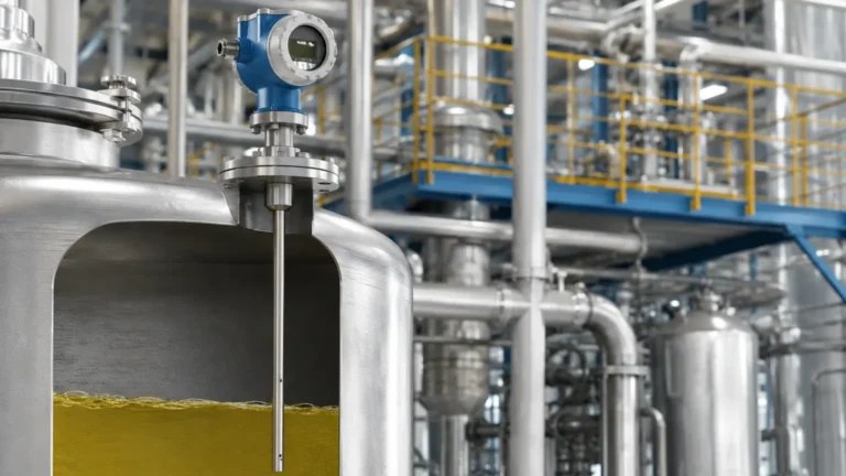
Radar Level Transmitter for Solids
Radar Level Transmitter for Solids: A Technical Guide to Selection and Installation
Measuring the level of bulk solids in silos, bunkers, and stockpiles presents a unique set of engineering challenges compared to liquid level measurement. Unlike liquids, which maintain a flat, horizontal surface, solids form irregular shapes, create significant dust during filling, and often possess low dielectric properties. For these reasons, the radar level transmitter for solids has become the preferred non-contact solution in industries ranging from cement and mining to food processing and chemical manufacturing.
This guide explores the underlying measurement principles of Radar Level Meters, selection criteria for different solid types, and the critical installation factors that ensure long-term reliability in harsh industrial environments.
Understanding the Measurement Principle
Radar level transmitters operate on the principle of Time Domain Reflectometry (TDR) or Frequency Modulated Continuous Wave (FMCW) technology. For bulk solids, FMCW is the industry standard due to its ability to provide a more stable signal in complex environments.
Time of Flight (ToF)
In its simplest form, the transmitter emits a high-frequency microwave pulse toward the material surface. The pulse reflects off the solid and returns to the sensor. By measuring the time it takes for the signal to travel to the surface and back (the "Time of Flight"), the device calculates the distance. Since the height of the vessel is known, the material level is easily determined.
FMCW vs. Pulse Radar
While pulse radar emits a burst and waits for a return, FMCW radar emits a continuous signal with a constantly changing frequency. The difference in frequency between the emitted and received signal is proportional to the distance. FMCW is generally superior for a radar level transmitter for solids because it offers a higher signal-to-noise ratio, which is vital when dealing with the signal scattering caused by uneven solid surfaces and heavy dust clouds.
Key Selection Criteria for Solids
Choosing the right radar instrument requires an analysis of the physical properties of the medium and the vessel geometry. The following factors are decisive:
1. Dielectric Constant (εr)
The dielectric constant of a material determines how much of the radar signal is reflected. Metals reflect 100% of the signal, while materials like plastic pellets, dry grains, or fly ash have low dielectric constants (εr < 2.0). If the dielectric constant is too low, the signal may pass through the material rather than reflecting off the surface. High-sensitivity radar units are required for materials with low reflectivity.
2. Particle Size and Surface Profile
Bulk solids can range from fine powders (cement, flour) to large lumps (ore, coal). Large, irregular lumps cause diffuse reflection, scattering the radar beam in multiple directions. Conversely, fine powders can create a flat but highly absorbent surface. The frequency of the radar must be matched to these surface characteristics.
3. Dust and Vapor
One of the primary advantages of radar over ultrasonic sensors is its immunity to dust. However, extremely dense dust during pneumatic filling can still attenuate the signal. High-frequency radar (80GHz) is typically better at penetrating dust than lower-frequency options because of its ability to focus the beam away from vessel walls and internal obstructions.
Selection Table: Radar Suitability by Material Type
| Material Type | Typical εr | Recommended Radar Frequency | Challenges |
| :— | :— | :— | :— |
| Cement/Powder | 2.0 – 3.0 | 80 GHz | Heavy dust, coating on antenna |
| Plastic Pellets | 1.1 – 1.5 | 80 GHz / High Sensitivity | Very low reflection |
| Coal/Ore | 3.0 – 10.0 | 26 GHz / 80 GHz | Large lumps, uneven surface |
| Grain/Cereals | 2.5 – 4.0 | 80 GHz | Dust, angle of repose |
| Fly Ash | 1.5 – 2.1 | 80 GHz | High temperature, fine dust |
Frequency Matters: 26GHz vs. 80GHz
In the world of Radar Level Meters, the choice of frequency is a critical engineering decision.
* 26GHz Radar: Traditionally the workhorse of the industry. It has a wider beam angle, which can be an advantage if the material surface is extremely turbulent, but a disadvantage in narrow silos where the beam might hit the walls or internal ladders.
* 80GHz Radar: The modern standard for a radar level transmitter for solids. The higher frequency allows for a much narrower beam angle (often as small as 3°). This precision allows the sensor to avoid internal obstructions like agitators or reinforcements and provides a stronger reflection from the material surface, even if it is angled.
Installation Guidelines and the Angle of Repose
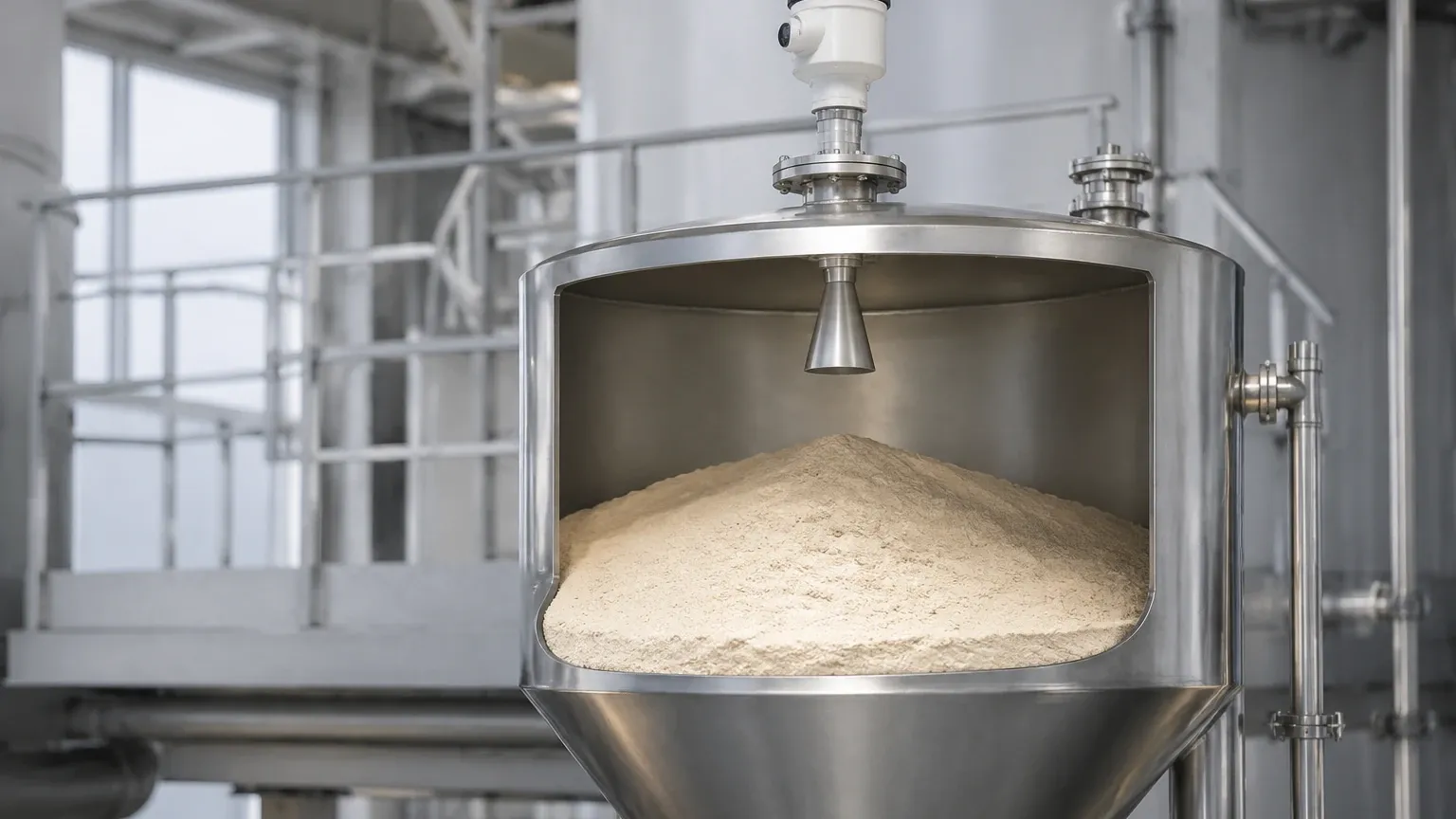
The most significant difference between liquid and solid measurement is the "Angle of Repose." When solids are poured into a silo, they form a cone. When they are discharged, they form a funnel (cone-down). This sloped surface reflects radar signals away from the sensor rather than directly back to it.
Mounting Position
To compensate for the angle of repose, the radar should generally be mounted at 1/6th to 1/3rd of the silo diameter from the wall. Mounting the sensor too close to the center may result in measuring the peak of the cone, while mounting too close to the wall can lead to interference from wall build-up or structural beams.
Aiming Flanges (Swivel Holders)
For solids applications, it is highly recommended to use an adjustable aiming flange or swivel holder. This allows the maintenance engineer to tilt the radar sensor to point directly at the material's slope, maximizing the returned signal strength. This is particularly important in tall, narrow silos where the signal loss due to the angle of repose can be significant.
Nozzle Design
The mounting nozzle should be as short as possible. If the nozzle is too long or narrow, the radar signal may reflect off the inside of the nozzle (ringing), creating a "dead zone" at the top of the tank where measurement is impossible.
Managing Application Risks and Limitations
While radar is highly versatile, engineers must be aware of specific limitations:
1. Antenna Coating: In applications like cement or moist grain, dust can accumulate on the antenna. While many radar level transmitters for solids are designed to ignore a certain amount of coating, excessive buildup will eventually attenuate the signal. Units with integrated air purging systems are recommended for these environments.
2. Internal Obstructions: Manways, ladders, and support struts can create "false echoes." Advanced radar software allows for "False Echo Suppression," where the device learns the position of fixed objects and ignores their reflections. However, the best practice remains selecting a narrow-beam 80GHz unit to avoid these objects entirely.
3. Extremely Low Dielectrics: For materials with a dielectric constant below 1.5, Guided Wave Radar (GWR) may be a more reliable choice than non-contact radar, as the probe guides the signal directly to the material, minimizing loss.
Buyer’s Guide: Confirming Specifications for International Procurement
When sourcing a radar level transmitter for solids for an industrial project, providing the manufacturer with accurate data is essential for a successful commissioning. International buyers should confirm the following parameters:
* Measuring Range: Define the total height of the vessel (e.g., 30m, 70m, or 120m).
* Process Temperature and Pressure: Standard units handle up to 80°C, but high-temperature versions with cooling fins can handle up to 250°C or more.
* Material Characteristics: Specify the chemical name, particle size, and whether the material is prone to sticking or generating static electricity.
* Output Requirements: Most industrial systems require a 4-20mA signal with HART protocol, though Modbus RS485 or Profibus are common in automated plants.
* Certifications: Ensure the device meets local safety standards, such as ATEX or IECEx for explosive dust environments (Ex ia or Ex d).
Frequently Asked Questions (FAQ)
Q: Can radar measure through plastic or glass windows?
A: Yes. Because radar uses electromagnetic waves, it can penetrate non-conductive materials. This allows for measurement through a PTFE or glass sight port if the process media is extremely corrosive or hazardous.
Q: How does moisture content affect solids measurement?
A: Moisture significantly increases the dielectric constant of a material. Generally, a moist solid is easier for a radar to detect than a bone-dry solid. However, moisture can also increase the likelihood of material sticking to the antenna.
Q: Is 80GHz always better than 26GHz?
A: For most solids applications, yes, due to the narrower beam and better dust penetration. However, 26GHz may still be used in shorter vessels or where a wider beam is needed to average out an extremely irregular surface.
Q: Do I need to empty the silo to calibrate the radar?
A: No. Modern radar level transmitters can be calibrated via software using the vessel dimensions. While a physical check at a known level is good practice for verification, it is not required for the initial setup.
By understanding these technical nuances, engineers and procurement professionals can ensure they select a radar level transmitter for solids that provides accurate, maintenance-free data, even in the most demanding bulk handling environments.