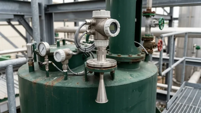
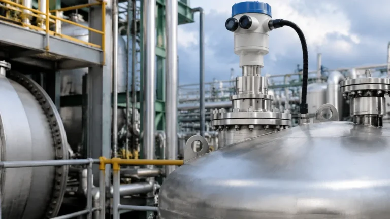
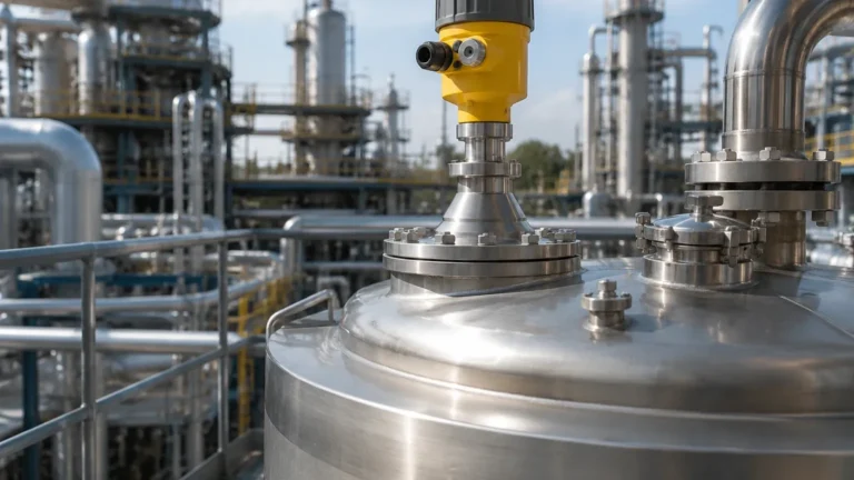
Radar Level Transmitter Parameters
Radar Level Transmitter Parameters: A Technical Guide for Industrial Engineering
In the landscape of industrial automation, the precision of level measurement directly impacts process safety, inventory management, and operational efficiency. Among the various technologies available, Radar Level Meters have emerged as the gold standard for non-contact measurement in challenging environments. Unlike ultrasonic sensors, which rely on sound waves and are susceptible to air temperature and pressure changes, radar technology utilizes electromagnetic waves that travel at the speed of light, offering unparalleled stability.
Selecting the correct instrument requires a deep understanding of specific radar level transmitter parameters. This guide provides a comprehensive technical overview of these parameters, the underlying measurement principles, and the engineering considerations necessary for successful deployment in B2B industrial applications.
1. Measurement Principles: How Radar Works
Before evaluating technical parameters, it is essential to distinguish between the two primary methods of radar level measurement: Pulse Radar and Frequency Modulated Continuous Wave (FMCW).
Pulse Radar (Time of Flight)
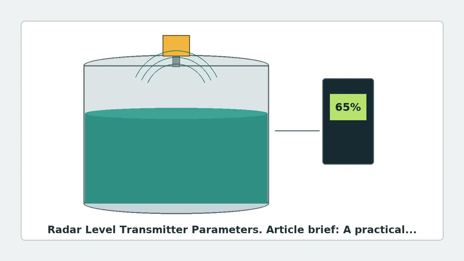
Pulse radar transmitters emit a short microwave pulse toward the product surface. The instrument measures the time it takes for the pulse to travel to the surface and return to the antenna. Since the speed of light is constant, the distance is calculated using the formula:
*Distance = (Speed of Light × Time of Flight) / 2*.
FMCW (Frequency Modulated Continuous Wave)
FMCW radar transmits a continuous signal with a constantly changing frequency. The frequency of the reflected signal is compared to the frequency of the signal being transmitted at that moment. The difference between these frequencies is directly proportional to the distance. FMCW is generally preferred for high-precision applications due to its superior signal-to-noise ratio and higher resolution.
For more information on specific hardware configurations, engineers can Review product options and application support to match these principles with their specific vessel requirements.
2. Core Radar Level Transmitter Parameters
When specifying a radar unit, several technical parameters dictate whether the device will function reliably in a given process. Below are the most critical factors an engineer must evaluate.
Frequency (GHz)
Frequency is perhaps the most significant parameter. Industrial radar typically operates in three bands:
* 6 GHz (C-Band): Best for applications with heavy foam or extreme turbulence, as the longer wavelength can penetrate surface disturbances.
* 26 GHz (K-Band): The versatile "all-rounder." It offers a balance between beam focus and the ability to handle moderate dust or vapor.
* 80 GHz (W-Band): The modern standard for high precision. It features a very narrow beam angle, making it ideal for small tanks with internal obstructions or for measuring through narrow nozzles.
Dielectric Constant (εr)
The dielectric constant of the medium is a measure of its ability to reflect electromagnetic waves.
* High εr (>10): Materials like water or aqueous solutions reflect signals strongly, making measurement easy.
* Low εr (1.4 to 4): Materials like hydrocarbons, oils, or plastic pellets reflect very little energy. For these materials, high-sensitivity radar or Guided Wave Radar (GWR) may be required.
Beam Angle
The beam angle is determined by the frequency and the antenna diameter. A narrower beam angle (common in 80 GHz units) reduces the risk of interference from tank walls, agitators, or heating coils.
Measurement Range and Dead Zone
* Range: The maximum distance the radar can measure (e.g., 30m, 70m, or 120m).
* Dead Zone (Blocking Distance): The area immediately below the antenna where measurement is not possible. This is typically between 50mm and 200mm, depending on the antenna design.
3. Engineering Selection Table
The following table compares common radar level transmitter parameters across different frequency ranges to assist in the initial selection process.
| Parameter | 6 GHz Radar | 26 GHz Radar | 80 GHz Radar |
| :— | :— | :— | :— |
| Typical Beam Angle | 20° – 30° | 8° – 12° | 3° – 6° |
| Accuracy | ±10 mm | ±2 mm to ±5 mm | ±1 mm |
| Smallest Nozzle Size | >150 mm (6") | >50 mm (2") | >20 mm (¾") |
| Foam Resistance | Excellent | Moderate | Low |
| Dust/Steam Penetration | High | Moderate | High (due to signal processing) |
| Application Focus | Large turbulent tanks | General process tanks | Small vessels, high precision |
4. Installation and Mounting Guidelines
Correct installation is as critical as selecting the right parameters. Even the most advanced Radar Level Meters will fail if mounted incorrectly.
Nozzle Placement
* The 1/6 Rule: For cylindrical tanks, the ideal mounting position is approximately 1/6th of the tank diameter from the outer wall.
* Avoid the Center: Never mount a radar in the exact center of a domed or flat-roof tank, as this can cause multiple reflections (parabolic effect) that interfere with the signal.
* Inlet Interference: Ensure the radar is not positioned directly above the product inlet to avoid measuring the falling stream instead of the liquid level.
0
Internal Obstructions
Agitators, ladders, and pipes create "false echoes." While modern software can perform a "False Echo Suppression" or "Background Masking" to ignore these reflections, it is best practice to provide a clear line of sight to the product surface.
Nozzle Height and Diameter
The antenna should ideally extend slightly below the mounting nozzle to prevent signal ringing within the nozzle itself. If the nozzle is very long and narrow, an 80 GHz radar is mandatory to keep the beam from hitting the nozzle walls.
5. Environmental and Process Constraints
Engineers must account for the physical state of the process when defining radar level transmitter parameters.
1. Pressure and Temperature: Standard radar units handle up to 40 bar and 150°C. High-pressure/high-temperature (HPHT) versions can reach 160 bar and 450°C using specialized ceramic or graphite seals.
2. Condensation and Buildup: In applications with heavy steam or viscous liquids that coat the antenna, a PTFE (Teflon) drip shield or a lens antenna is recommended. Some units allow for a purging connection to blow compressed air across the antenna face.
3. Vacuum Conditions: Radar works perfectly in a vacuum because electromagnetic waves do not require a medium for travel, unlike ultrasonic waves.
6. International Buyer’s Checklist: Procurement Parameters
When sourcing equipment for global projects, international buyers should confirm the following technical specifications with the manufacturer:
* Output Signals: Is the standard 4-20mA with HART sufficient, or is a digital bus like RS485 Modbus, Profibus, or Foundation Fieldbus required?
* Hazardous Area Certifications: Does the site require ATEX (Europe), IECEx (Global), or CSA/UL (North America) explosion-proof or intrinsically safe ratings?
* Process Connection Standards: Ensure the flange or thread matches local standards (e.g., DN80 PN16 vs. 3" ANSI 150lb).
* Housing Material: For corrosive environments (e.g., offshore or chemical plants), 316L stainless steel housing is preferred over aluminum.
* Ingress Protection: A minimum of IP66/IP67 is standard, but IP68 may be required for flood-prone areas.
7. Frequently Asked Questions (FAQ)
Q: Can radar measure the level of solids like sand or grain?
A: Yes. However, solids often have a low dielectric constant and an uneven surface (angle of repose). High-frequency 26 GHz or 80 GHz radars with specialized algorithms for solids are recommended for these applications.
Q: How does foam affect radar measurement?
A: It depends on the foam density. Light, airy foam may be transparent to radar, allowing it to measure the liquid level underneath. Thick, dense, or metallic foam may reflect the signal, causing the radar to measure the top of the foam. In such cases, lower frequency (6 GHz) radar is more effective at penetration.
Q: What is the difference between 2-wire and 4-wire radar?
A: 2-wire units are powered by the 4-20mA current loop, simplifying wiring. 4-wire units have a separate power supply, which is often necessary for older high-power FMCW units or when integrated heating elements are used.
Q: Is a stilling well necessary for radar?
A: A stilling well (a pipe inside the tank) is used to eliminate surface turbulence and foam. It is also used for materials with very low dielectric constants to concentrate the radar energy. However, for most modern 80 GHz applications, a stilling well is no longer required due to the narrow beam focus.
Conclusion
Understanding radar level transmitter parameters is the foundation of reliable process instrumentation. By carefully matching frequency, beam angle, and antenna design to the specific dielectric and physical properties of the medium, engineers can ensure high-accuracy measurements even in the most demanding industrial environments. For those seeking to implement these solutions, selecting a manufacturer that offers both technical expertise and customizable options is essential for long-term project success.