Radar Level Transmitter PDF
Radar Level Transmitter PDF
In the field of industrial process automation, selecting the correct instrumentation is critical for operational safety, efficiency, and inventory accuracy. Among the various technologies available, radar level measurement has emerged as a premier solution for both liquid and solid applications. Engineers and procurement specialists often search for a radar level transmitter pdf to access technical specifications, installation diagrams, and performance curves. This article serves as a comprehensive technical reference, consolidating the essential engineering data required to understand, select, and deploy radar level measurement systems effectively.
Understanding Radar Level Measurement Principles
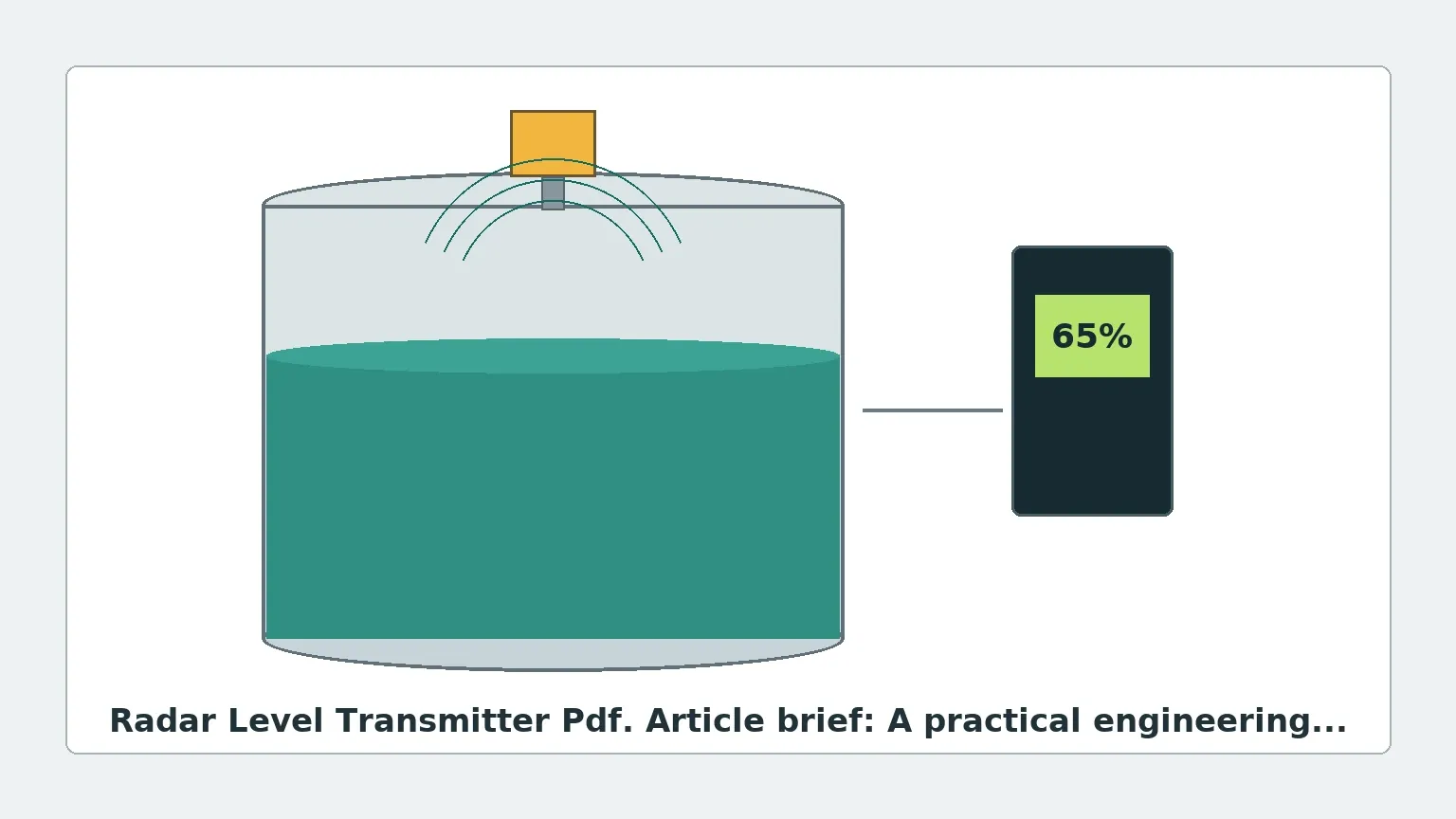
Before consulting a radar level transmitter pdf for specific model numbers, it is essential to understand the underlying physics of radar technology. Radar level meters operate on the principle of Time Domain Reflectometry (TDR) or Frequency Modulated Continuous Wave (FMCW). They emit electromagnetic pulses or continuous waves that travel at the speed of light. When these waves encounter a medium with a different dielectric constant ($ε_r$) than the air or vapor space, a portion of the energy is reflected back to the sensor.
1. Pulse Radar (Non-Contact)
Pulse radar transmitters emit a short microwave signal and measure the time it takes for the pulse to travel to the product surface and back. This "time-of-flight" is directly proportional to the distance. While robust, pulse radar typically offers lower precision compared to modern FMCW systems.
2. FMCW Radar (Non-Contact)
Frequency Modulated Continuous Wave (FMCW) radar is the current industry standard for high-accuracy applications. Instead of pulses, the transmitter sends a continuous signal with a constantly changing frequency. The difference in frequency between the transmitted signal and the reflected signal is proportional to the distance. Modern 80GHz Radar Level Meters utilize FMCW to provide millimeter-level precision, even in complex environments.
3. Guided Wave Radar (GWR)
Guided Wave Radar is a contact-based technology where the microwave signal is directed along a physical probe (cable or rod). This technology is particularly effective for low dielectric liquids, high-turbulence surfaces, or applications involving heavy foam, as the probe concentrates the signal energy.
Frequency Selection: 6GHz, 26GHz, and 80GHz
One of the most critical data points found in a radar level transmitter pdf is the operating frequency. The frequency determines the beam angle, the size of the antenna, and the instrument's ability to penetrate dust or steam.
* 6GHz Radar: These low-frequency devices are less affected by foam or heavy vapors. However, they require very large antennas to achieve a narrow beam, making them less common in modern compact tanks.
* 26GHz Radar: A versatile mid-range frequency suitable for many liquid applications. It offers a balance between antenna size and signal strength, though it may struggle with heavy dust in solids applications.
* 80GHz Radar: The current state-of-the-art. High frequency allows for extremely narrow beam angles (as low as 3 degrees), which minimizes interference from tank internals like agitators or ladders. It is the preferred choice for narrow silos and high-precision liquid measurement.
Comparison Table: Radar Frequency Characteristics
| Feature | 6 GHz | 26 GHz | 80 GHz |
| :— | :— | :— | :— |
| Beam Angle | Wide (approx. 20°-30°) | Medium (approx. 8°-12°) | Narrow (approx. 3°-6°) |
| Antenna Size | Large | Medium | Small/Compact |
| Accuracy | ±10 mm | ±3 mm to ±5 mm | ±1 mm |
| Dust/Steam Resistance | Excellent | Good | Moderate (requires purging) |
| Best Use Case | Heavy foam/vapor | General liquid storage | Narrow tanks, high precision |
Selection Criteria for Industrial Applications
When evaluating a radar level transmitter pdf for a specific project, engineers must match the instrument specifications to the process conditions. The following factors are decisive:
Dielectric Constant ($ε_r$)
The dielectric constant of the material being measured is the most important factor in signal reflection. Materials with high dielectric constants (e.g., water, $ε_r ≈ 80$) reflect signals strongly. Hydrocarbons and oils have low dielectric constants ($ε_r ≈ 1.9$ to $4.0$), which produce weaker reflections. If the dielectric constant is below 1.4, Guided Wave Radar or high-sensitivity 80GHz FMCW radar is typically required.
Process Temperature and Pressure
Standard radar transmitters can handle temperatures up to 150°C (302°F) and pressures up to 4 MPa (40 bar). For extreme applications, such as molten salts or high-pressure reactors, specialized high-temperature versions with ceramic seals and cooling fins are necessary. Always verify the "Pressure vs. Temperature" curve in the technical documentation.
Tank Geometry and Internals
Internal obstructions like heating coils, agitators, and reinforcement struts can create "false echoes." While modern software can perform "false echo suppression" (mapping out the tank to ignore static reflections), choosing an 80GHz radar with a narrow beam often eliminates the problem at the source by avoiding the obstructions entirely.
Installation Guidelines and Best Practices
Correct installation is paramount to the performance of Radar Level Meters. Most performance issues reported in the field are the result of improper mounting rather than instrument failure.
1. Nozzle Height and Diameter: The antenna should ideally extend slightly beyond the mounting nozzle to prevent signal ringing within the nozzle itself. If the nozzle is long, a waveguide extension may be required.
2. Mounting Position: The transmitter should never be mounted in the center of a tank (to avoid multiple reflections from the tank walls) or too close to the wall (to avoid signal interference). A common rule of thumb is to mount the sensor at 1/6th to 1/4th of the tank diameter from the wall.
3. Inflow Streams: Never mount the radar directly above the filling inlet. The turbulence and the falling stream of material will interfere with the microwave signal and lead to erratic readings.
4. Agitators: If the tank has an agitator, the radar should be positioned so the beam does not hit the blades. If this is unavoidable, the transmitter must be synchronized or programmed with a sophisticated echo-tracking algorithm.
Limitations and Risks
While radar is a highly versatile technology, it is not a universal solution. Engineers should be aware of the following limitations:
* Heavy Foam: Extremely thick, dense foam can absorb the radar signal entirely, preventing any reflection from the liquid surface. In these cases, Guided Wave Radar or differential pressure transmitters may be more reliable.
* Vacuum Conditions: While radar works in a vacuum (as microwaves do not require a medium for travel), the mechanical seals of the transmitter must be rated for vacuum service to prevent air ingress or sensor damage.
* Caking and Buildup: If the material is prone to sticking (e.g., wet lime or heavy resins), buildup on the antenna can attenuate the signal. Many modern radar units feature a "lens" antenna made of PTFE to minimize adhesion, or provide a flushing connection for periodic cleaning.
Frequently Asked Questions (FAQ)
Q: Can a radar level transmitter measure the interface between two liquids?
A: Yes, but this typically requires Guided Wave Radar (GWR). The microwave signal reflects off the upper liquid (low dielectric) and continues through to reflect off the lower liquid (high dielectric). The upper layer must be non-conductive and have a lower dielectric constant than the lower layer.
Q: Is 80GHz always better than 26GHz?
A: Not necessarily. While 80GHz offers better precision and a narrower beam, 26GHz is often more cost-effective for large, simple storage tanks where high precision is not required. Additionally, lower frequencies can sometimes perform better in extremely dusty environments where high-frequency signals might be scattered.
Q: How do I perform a field calibration?
A: Most modern transmitters are pre-calibrated at the factory. Field calibration usually involves setting the "Zero" (empty tank) and "Span" (full tank) points via a HART communicator, a local display, or a Bluetooth-connected mobile app. Always refer to the specific radar level transmitter pdf for the manufacturer's menu structure.
Conclusion for International Buyers
When sourcing level measurement equipment for industrial projects, it is vital to look beyond the basic price point. A reliable manufacturer should provide comprehensive documentation, including a detailed radar level transmitter pdf that covers certificates (ATEX, IECEx, SIL2), material traceability, and precise technical drawings.
By understanding the measurement principles and strictly adhering to installation constraints, engineers can ensure that their Radar Level Meters provide years of maintenance-free service. Whether dealing with corrosive chemicals in the water treatment industry or abrasive solids in mining, the correct application of radar technology remains one of the most effective ways to achieve precise process control.