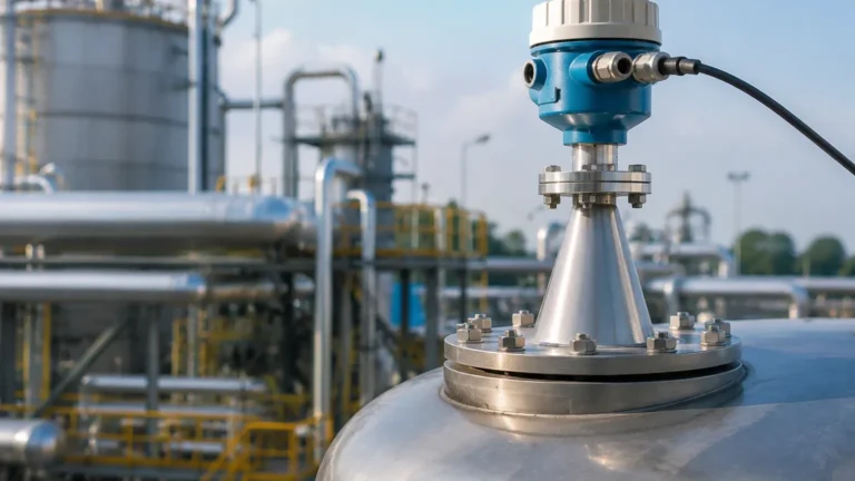
Radar Level Transmitter Range
Radar Level Transmitter Range: An Engineering Guide to Selection and Application
In industrial process control, the accuracy and reliability of level measurement are paramount. Among the various technologies available, radar level transmitters have emerged as a preferred solution for non-contact measurement in challenging environments. However, specifying the correct equipment requires a deep understanding of the radar level transmitter range and the variables that influence signal integrity over distance.
This guide examines the technical principles of radar measurement, the factors determining effective range, and the practical considerations engineers must address when selecting Radar Level Meters for industrial applications.
Understanding Radar Measurement Principles
Before evaluating range specifications, it is essential to understand how radar instruments calculate distance. Industrial radar level transmitters generally operate using one of two primary methods: Pulse Radar or Frequency Modulated Continuous Wave (FMCW).
Pulse Radar (Time of Flight)
Pulse radar instruments emit short microwave pulses toward the surface of the medium. The device measures the time it takes for the pulse to travel to the surface and reflect back to the sensor. Since the speed of light is constant, the distance is calculated as:
*Distance = (Speed of Light × Time of Flight) / 2*
Pulse radar is often chosen for its lower power consumption and suitability for simple liquid level applications. However, its signal-to-noise ratio can be lower than FMCW, which may limit its effective range in environments with heavy vapor or turbulence.
FMCW (Frequency Modulated Continuous Wave)
FMCW radar transmits a continuous signal with a constantly changing frequency. The reflection from the product surface is received and compared to the frequency being transmitted at that exact moment. The difference between the transmitted and received frequencies is proportional to the distance.
FMCW technology typically offers higher precision and a more robust signal, making it the standard for long-range measurements (up to 120 meters) and complex solids applications where the reflection signal may be weak.
Defining the Radar Level Transmitter Range
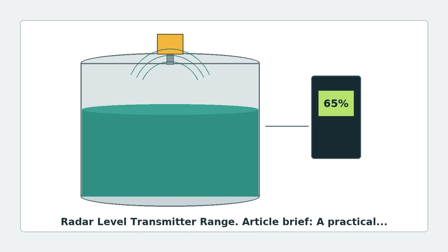
When reviewing a datasheet, the "range" is often presented as a single maximum value (e.g., 30m, 70m, or 100m). In practice, the radar level transmitter range is a dynamic performance envelope influenced by the installation environment and the material being measured.
Maximum vs. Effective Range
The maximum range listed by manufacturers represents the device's capability under ideal conditions: a flat, highly reflective surface (like water) in a calm environment. The effective range is the actual distance the transmitter can reliably measure in a specific application, accounting for signal attenuation, surface agitation, and the dielectric properties of the material.
Key Factors Influencing Range Performance
Several technical factors dictate how far a radar signal can travel and still return a readable echo.
1. Operating Frequency
The frequency of the radar signal significantly impacts both the range and the beam angle. Industrial radars typically operate in three bands:
* 6 GHz (C-Band): These low-frequency radars have a wide beam angle and are highly resistant to foam, dust, and vapor. However, they require large antennas and are generally limited to shorter ranges (up to 30m) due to lower signal focusing.
* 26 GHz (K-Band): The industry standard for many years, 26 GHz radars offer a balance between antenna size and range (up to 70-80m). They are suitable for most liquid and solid applications but can be affected by heavy steam or condensation.
* 80 GHz (W-Band): The latest advancement in radar technology. The high frequency allows for a very narrow beam angle (as small as 3°) and high signal focus. This enables measurement ranges of 120 meters or more, even in narrow tanks with internal obstructions.
2. Dielectric Constant (Dk)
The Dielectric Constant of the medium is perhaps the most critical factor in determining effective range. It represents the ability of a material to reflect microwave energy.
* High Dk Materials (Dk > 10): Water-based liquids reflect almost all the radar energy, allowing the transmitter to reach its maximum rated range.
* Low Dk Materials (Dk < 2): Hydrocarbons, oils, and some plastic pellets reflect very little energy. Much of the signal passes through the material or is absorbed. In these cases, the effective range of the transmitter may be reduced by 50% or more unless a high-sensitivity FMCW unit is used.
3. Antenna Type and Size
The antenna concentrates the radar energy. A larger horn antenna or a specialized lens antenna produces a narrower beam with higher gain, which extends the reachable range and improves the signal-to-noise ratio.
Technical Selection Guide
The following table provides a general reference for selecting radar technology based on range and application requirements.
| Application Type | Recommended Frequency | Typical Max Range | Key Advantage |
| :— | :— | :— | :— |
| Small Liquid Tanks | 26 GHz / 80 GHz | 20m – 30m | High precision, small process connections. |
| Large Storage Tanks | 80 GHz | 100m+ | Narrow beam avoids wall interference. |
| Corrosive Liquids | 26 GHz (PTFE Sealed) | 30m | Chemical resistance with reliable range. |
| High Dust Silos | 80 GHz / 26 GHz | 70m – 120m | Signal penetrates dust; narrow beam avoids internal structures. |
| Heavy Foam/Vapor | 6 GHz | 35m | Low frequency penetrates surface disturbances. |
Installation and Mounting Constraints
To maximize the radar level transmitter range and accuracy, engineers must adhere to specific installation guidelines.
The Dead Zone (Blocking Distance)
Every radar transmitter has a "dead zone" or "near-field" directly below the antenna (typically 50mm to 500mm). The device cannot accurately measure levels within this zone. When calculating the required range, ensure the maximum fill level of the tank does not enter the dead zone.
Beam Angle and Obstructions
The radar signal spreads as it travels. If the beam hits a tank wall, ladder, or agitator, it creates a parasitic reflection (noise) that can mask the true level signal.
* Calculation: The beam diameter can be calculated using the formula: *D = 2 × Range × tan(Beam Angle / 2)*.
* Solution: For tall, narrow silos, an 80 GHz transmitter with a 3° beam angle is often required to ensure the signal reaches the bottom without interference.
Nozzle Mounting
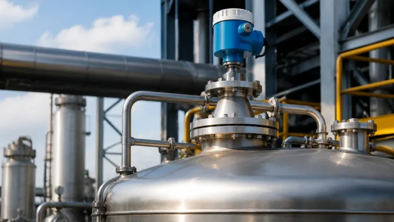
The transmitter should be mounted such that the antenna extends slightly past the bottom of the mounting nozzle. If the antenna is recessed, the nozzle itself will cause reflections that reduce the effective sensitivity and range of the device.
Application Limitations and Environmental Challenges
While Radar Level Meters are highly versatile, certain conditions can limit their performance:
1. Extreme Turbulence: A boiling or heavily agitated liquid surface scatters the radar signal. This scattering reduces the energy returned to the sensor, effectively shortening the measurable range.
2. Heavy Foam: Some types of foam are dense enough to reflect the signal (measuring the top of the foam), while others are transparent or absorb the signal entirely. Low-frequency (6 GHz) radar is generally better at penetrating foam to reach the liquid level.
3. Condensation and Buildup: Material buildup on the antenna can attenuate the signal. For long-range applications, antennas with a flat, self-cleaning lens design (common in 80 GHz units) are preferred to prevent signal loss.
Frequently Asked Questions (FAQ)
Q: Does the pressure or temperature inside the tank affect the radar range?
A: Unlike ultrasonic sensors, radar waves are electromagnetic and do not require a medium for travel. Therefore, changes in air temperature, pressure, or vacuum do not affect the speed of the signal or the measurement range. However, the physical limits of the transmitter's housing and seals must be rated for the process conditions.
Q: Can I use a radar transmitter to measure through a plastic tank wall?
A: Yes, if the tank is made of a non-conductive material like PE, PP, or GRP, the radar signal can pass through the wall. This allows for non-invasive measurement, though the signal range will be slightly reduced due to the attenuation caused by the wall material.
Q: What is the minimum Dielectric Constant a radar can measure?
A: High-performance FMCW radar transmitters can often measure materials with a Dk as low as 1.4. For materials with a lower Dk, a guided wave radar (GWR) or a specialized high-sensitivity non-contact radar is usually required.
Q: How do I choose between a 26 GHz and an 80 GHz transmitter for a 50-meter silo?
A: While both can technically reach 50 meters, the 80 GHz unit is usually the better choice for solids. Its narrower beam prevents reflections from the silo walls and internal bracing, providing a much cleaner signal at the bottom of the range.
Conclusion
Selecting the appropriate radar level transmitter range involves more than matching a distance requirement to a datasheet. It requires a holistic evaluation of the frequency, the dielectric properties of the medium, and the physical geometry of the vessel. By understanding these engineering boundaries, B2B buyers and plant engineers can ensure they specify a solution that provides accurate, maintenance-free level measurement across the entire process cycle. For complex applications, consulting with a specialized manufacturer like Welk ensures that the selected instrumentation is optimized for the specific challenges of the industrial environment.