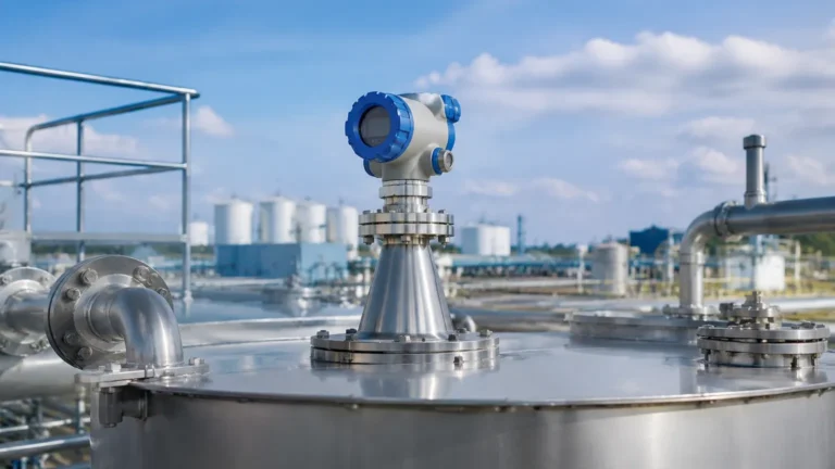
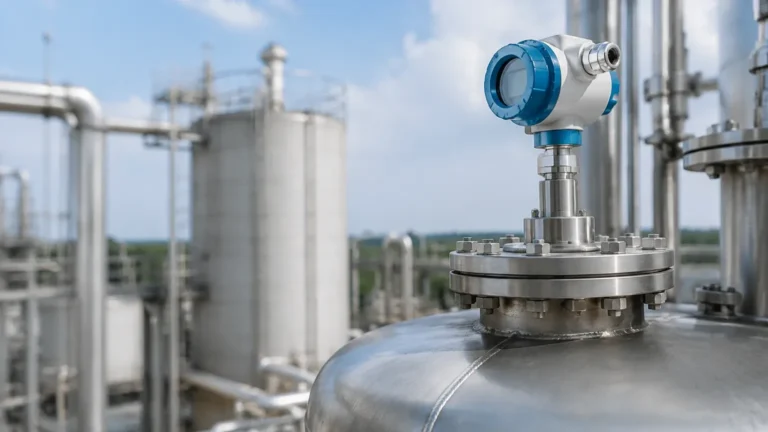
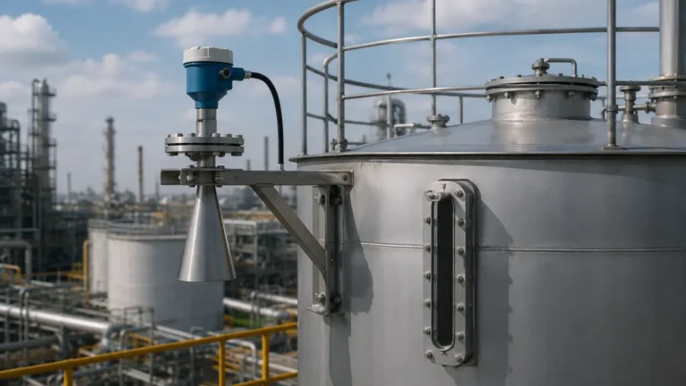
Lr150 Radar Level Transmitter
Engineering Guide to the LR150 Radar Level Transmitter in Industrial Applications
In the landscape of industrial process automation, the accuracy of level measurement directly impacts operational safety, inventory management, and cost efficiency. Among the various technologies available, Radar Level Meters have emerged as the preferred solution for non-contact measurement. Specifically, the lr150 radar level transmitter represents a significant advancement in high-frequency radar technology, offering precision and reliability in challenging environments. This article provides a comprehensive technical analysis of the LR150, its operating principles, selection criteria, and installation requirements for engineering professionals.
Understanding Radar Measurement Principles
Before selecting a specific instrument like the lr150 radar level transmitter, it is essential to understand the physics governing radar level measurement. Radar sensors generally operate using one of two primary methods: Pulse Radar or Frequency Modulated Continuous Wave (FMCW).
Time of Flight (ToF) and Pulse Radar
Pulse radar systems emit a short microwave signal toward the medium's surface. The sensor measures the time it takes for the pulse to travel to the surface and return. Since the speed of light is constant, the distance is calculated as:
*Distance = (Speed of Light × Travel Time) / 2*
Frequency Modulated Continuous Wave (FMCW)
Modern high-performance transmitters, including many variants in the 80 GHz range like the LR150, often utilize FMCW technology. Instead of a single pulse, the transmitter emits a continuous signal with a constantly changing frequency. The difference between the frequency of the emitted signal and the reflected signal is proportional to the distance. FMCW offers superior signal-to-noise ratios and higher accuracy, especially in environments with turbulence or low-dielectric materials.
The Role of Frequency (80 GHz vs. 24 GHz)
The lr150 radar level transmitter typically operates at a high frequency, often in the 80 GHz band. Higher frequency allows for a much narrower beam angle. A narrow beam (often as small as 3 to 4 degrees) minimizes interference from tank walls, internal ladders, or agitators, making it ideal for narrow vessels or complex geometries.
Technical Specifications and Features of the LR150
The LR150 is designed as a compact, versatile transmitter for both liquid and solid level measurement. Its engineering profile usually includes the following characteristics:
* Measurement Range: Typically up to 15 meters (approx. 49 feet) or 30 meters depending on the specific model configuration.
* Accuracy: High precision, often within ±2 mm.
* Beam Angle: Narrow beam (approx. 4° to 8°) due to the high-frequency signal.
* Process Connections: Options for threaded (G1½", 1½" NPT) or flanged connections.
* Housing Materials: Often constructed from PVDF or Stainless Steel for corrosion resistance.
* Output Signals: Standard 4-20 mA with HART protocol for digital integration into PLC/SCADA systems.
Selection Criteria: When to Choose the LR150
Selecting the correct instrument requires an evaluation of the medium properties and the vessel environment. The following table compares the LR150 style high-frequency radar against traditional low-frequency radar and ultrasonic sensors.
Technology Comparison Table
| Feature | LR150 Radar (80 GHz) | Traditional Radar (24 GHz) | Ultrasonic Sensors |
| :— | :— | :— | :— |
| Beam Angle | Very Narrow (4°-8°) | Moderate (15°-30°) | Wide (10°-15°) |
| Accuracy | ±2 mm | ±5 mm to ±10 mm | ±0.25% of range |
| Dust/Vapor Resistance | Excellent | Good | Poor |
| Tank Obstructions | Easily bypassed | May cause false echoes | Significant interference |
| Dielectric Sensitivity | High sensitivity | Moderate sensitivity | N/A (Mechanical wave) |
| Cost | Mid-to-High | Moderate | Low |
Practical Application Scenarios
1. Chemical Storage: The lr150 radar level transmitter is highly effective for corrosive acids and bases where non-contact measurement is mandatory. Its PVDF housing options provide longevity against chemical vapors.
2. Water and Wastewater: In pumping stations or wet wells, the narrow beam allows the sensor to be mounted in tight spaces without reflecting off the walls or pump hardware.
3. Food and Beverage: The high frequency allows for accurate measurement through foam (to an extent) and provides a hygienic solution when used with appropriate process connections.
Installation Considerations and Constraints
Correct installation is the most critical factor in ensuring the long-term reliability of a radar level meter. Engineers must adhere to specific geometric constraints to avoid signal degradation.
1. Mounting Position
The transmitter should be mounted at least 200 mm from the tank wall. Mounting it too close to the wall can cause the microwave signal to interact with the vessel boundary, leading to false echoes. However, it should not be mounted in the exact center of a domed-roof tank, as this can concentrate parasitic reflections.
2. Nozzle Height and Diameter
For the lr150 radar level transmitter, the nozzle should be as short as possible. If the nozzle is too long or too narrow, the radar signal may reflect off the internal edges of the nozzle before even entering the tank. Ideally, the antenna should extend slightly beyond the bottom of the nozzle.
3. Avoiding Obstructions
Internal structures such as heating coils, agitator blades, and ladders must be outside the radar's signal cone. Because the LR150 has a narrow beam angle, it is much easier to find a "clear path" to the liquid surface than with lower-frequency models.
4. The Blind Zone (Dead Band)
Every radar transmitter has a minimum measurable distance, known as the blind zone or blocking distance, typically located directly below the antenna (e.g., 50 mm to 100 mm). The maximum level of the medium should never reach into this zone, as the sensor will lose the ability to track the surface.
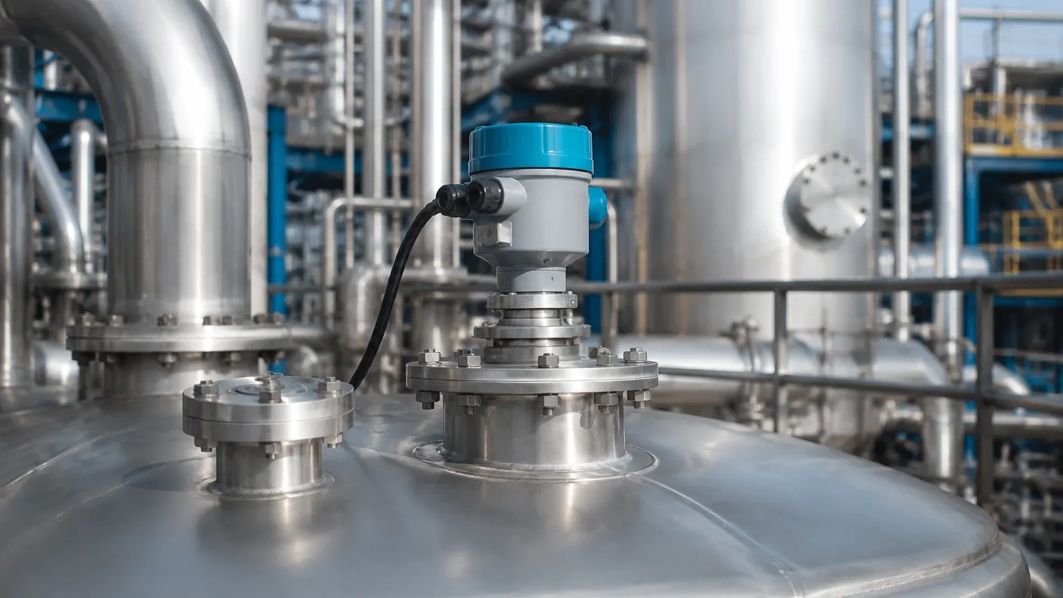
Limitations and Risk Management
While the lr150 radar level transmitter is a robust tool, engineers must be aware of its physical limitations:
* Low Dielectric Constants (εr): Materials with very low dielectric constants (like certain oils or liquefied gases) reflect less energy. In these cases, a guided wave radar or a larger antenna may be required to amplify the signal return.
* Heavy Foam: While high-frequency radar can penetrate some light foam, extremely thick or dense foam (like that found in some fermentation processes) may absorb the radar signal entirely, resulting in a "loss of echo" error.
* Condensation and Buildup: Although 80 GHz radars handle condensation better than older models, heavy crystalline buildup on the antenna lens can attenuate the signal. Regular inspection or the use of a purging system may be necessary in extreme environments.
Maintenance and Troubleshooting
Radar transmitters are generally low-maintenance because they have no moving parts. However, a proactive maintenance schedule should include:
1. Visual Inspection: Check for physical damage to the housing or process connection.
2. Echo Curve Analysis: Most modern Radar Level Meters allow users to view the echo curve via HART or a local display. Engineers should save a "baseline" echo curve of an empty tank to identify and map out fixed obstructions (False Signal Suppression).
3. Cleaning: If the medium is prone to coating, the antenna lens should be cleaned periodically with a soft cloth and compatible solvent.
Frequently Asked Questions (FAQ)
Q: Can the LR150 be used for solids like grain or plastic pellets?
A: Yes. The high frequency and narrow beam of the lr150 radar level transmitter make it suitable for solids, which often have uneven surfaces. However, the range may be reduced compared to liquid applications due to the diffuse reflection of the signal.
Q: Does pressure or temperature in the tank affect the measurement?
A: Unlike ultrasonic sensors, which depend on the speed of sound (which changes with air density), radar signals are electromagnetic and are virtually unaffected by temperature, pressure, or vacuum conditions within the vessel.
Q: How do I handle a tank with a heavy agitator?
A: The LR150 features software algorithms for "False Signal Suppression." By recording the reflections from the agitator while the tank is empty, the transmitter can "ignore" those specific signals during normal operation.
Conclusion
The lr150 radar level transmitter represents a high-tier solution for industrial level sensing, balancing precision with a compact form factor. By utilizing 80 GHz technology, it overcomes many of the traditional hurdles associated with narrow tanks and internal obstructions. For international buyers and plant engineers, success lies in matching the transmitter’s specifications—such as beam angle and material compatibility—to the specific chemical and physical properties of the process medium.
When properly installed and configured, these instruments provide a maintenance-free, highly accurate window into process inventory, ensuring that industrial operations remain both safe and efficient. For further technical specifications and to explore various configuration options, engineers should review product options and application support to ensure the selected hardware meets the specific demands of their facility.