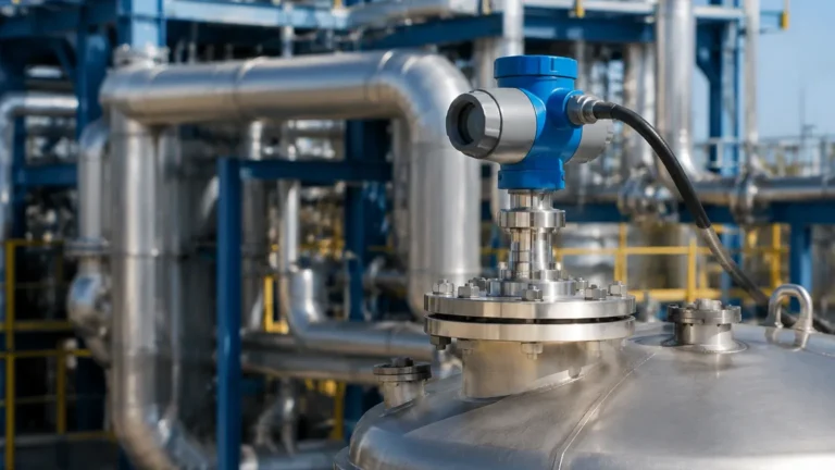
Cone Antenna Radar Level Transmitter
Cone Antenna Radar Level Transmitter: A Technical Engineering Guide
In the landscape of industrial process automation, precise level measurement is a cornerstone of operational efficiency and safety. Among the various technologies available, Radar Level Meters have emerged as a preferred solution for non-contact measurement in challenging environments. Specifically, the cone antenna radar level transmitter—often referred to as a horn antenna radar—serves as the workhorse for liquid and solid level detection in tanks, silos, and process vessels.
This guide provides a detailed technical analysis of the operating principles, selection criteria, and installation requirements for cone antenna radar systems, aimed at helping engineers and procurement professionals make informed decisions for their specific applications.
1. Measurement Principles of Radar Level Technology
Radar level transmitters operate on the principle of electromagnetic wave propagation. Unlike ultrasonic sensors, which rely on sound waves and are susceptible to air temperature and pressure changes, radar waves travel at the speed of light and are largely unaffected by the vapor space composition.
Time of Flight (ToF) and FMCW
Most modern cone antenna radar level transmitters utilize one of two primary methods for distance calculation:
1. Pulse Radar: The instrument emits a short microwave pulse toward the product surface. The time it takes for the pulse to travel to the surface and back (the Time of Flight) is measured. Since the speed of light is constant, the distance is calculated as:
*Distance = (Speed of Light × Time) / 2*.
2. Frequency Modulated Continuous Wave (FMCW): The transmitter emits a continuous signal with a constantly changing frequency. The difference in frequency between the emitted signal and the reflected signal is proportional to the distance. FMCW is generally preferred for high-precision applications and environments with significant noise or turbulence.
The Role of the Cone Antenna
The cone antenna acts as a waveguide that transitionally matches the impedance of the radar electronics to the free space of the tank. Its primary function is to focus the microwave energy into a narrow beam. A well-designed cone antenna minimizes "side lobes"—stray energy that can reflect off tank walls or internal obstructions—thereby increasing the Signal-to-Noise Ratio (SNR).
2. Technical Characteristics of Cone Antennas
The geometry of the cone antenna radar level transmitter is not merely aesthetic; it is a critical factor in the instrument's performance.
Beam Angle and Gain
There is an inverse relationship between the diameter of the cone and the beam angle. A larger cone diameter produces a narrower beam. For instance, a 100 mm (4-inch) cone antenna typically offers a narrower beam angle (e.g., 8° to 10°) compared to a 50 mm (2-inch) cone (e.g., 18° to 20°).
Narrower beams are advantageous in tall, narrow tanks or vessels with internal structures like agitators, heating coils, or ladders, as they reduce the likelihood of false echoes.
Frequency Bands
Cone antennas are commonly used with two main frequency ranges:
* 26 GHz (K-band): The industry standard for many years. It offers a good balance between beam focusing and the ability to penetrate light foam or dust.
* 80 GHz (W-band): The latest evolution in radar technology. Due to the shorter wavelength, 80 GHz transmitters can achieve extremely narrow beam angles even with small antenna sizes, making them ideal for small process connections.
3. Selection Criteria for Industrial Applications
When specifying a cone antenna radar level transmitter, several factors must be evaluated to ensure long-term reliability.
Dielectric Constant (εr)
The reflectivity of the target material is determined by its dielectric constant. Materials with high dielectric constants (e.g., water, εr ≈ 80) reflect radar waves strongly. Hydrocarbons and oils (εr ≈ 2.0 to 2.5) reflect much less energy. For low-dielectric materials, a larger cone antenna or a more sensitive FMCW transmitter is often required to capture a usable signal.
Process Conditions
* Temperature and Pressure: Cone antennas are typically constructed from stainless steel (316L) with internal components made of PTFE or PEEK. High-temperature versions can handle up to 250°C or higher with specialized cooling fins.
* Corrosive Media: For highly aggressive chemicals, the cone can be lined with PTFE or manufactured from exotic alloys like Hastelloy.
Selection Table: Antenna Comparison
| Feature | Cone (Horn) Antenna | Rod Antenna | Parabolic Antenna |
| :— | :— | :— | :— |
| Primary Use | General liquids/solids | Corrosive liquids/Small nozzles | Long-range/Low dielectric solids |
| Beam Focus | Good | Moderate | Excellent |
| Buildup Resistance | Moderate | High | Low |
| Standard Sizes | 40 mm to 150 mm | 20 mm to 50 mm | 200 mm+ |
| Max Range | Up to 70m | Up to 20m | Up to 100m |
4. Installation Considerations and Constraints
Proper installation is the most critical factor in preventing measurement errors. Even the most advanced radar level meters will fail if placed incorrectly.
Nozzle Geometry
The cone antenna should ideally extend beyond the mounting nozzle. If the cone is recessed inside a long, narrow nozzle, the radar signal will reflect off the nozzle walls, creating a large "ringing" effect or false echo near the top of the tank. This area is known as the Dead Zone or Blocking Distance.
* Rule of Thumb: The cone tip should protrude at least 10 mm to 20 mm below the bottom of the nozzle.
Tank Placement
* Avoid the Center: Do not mount the transmitter in the exact center of a domed-top tank, as this can concentrate multiple reflections (parabolic effect) and cause signal instability.
* Wall Clearance: Maintain a minimum distance from the tank wall (typically 1/6th of the tank diameter) to prevent beam interference.
* Obstructions: Ensure the beam path is clear of agitators, spray balls, and inflow streams. If an obstruction is unavoidable, many modern transmitters offer "False Echo Suppression" software to digitally ignore these fixed reflections.

5. Limitations and Application Risks
While highly versatile, the cone antenna radar level transmitter is not a universal solution. Engineers must be aware of the following risks:
1. Heavy Condensation: While radar can see through vapor, heavy droplets forming on the antenna lens can attenuate the signal. In these cases, a transmitter with a "drip-off" lens design or an air purging connection is recommended.
2. Heavy Foam: Thick, dense foam (like shaving cream) can absorb the radar signal entirely, leading to a "Loss of Echo" (LOE) error. For such applications, Guided Wave Radar (GWR) is often a better alternative.
3. Solid Buildup: In applications involving sticky resins or dusty powders, material can accumulate inside the cone. This changes the impedance and degrades performance. Regular maintenance or the use of a dust cover/purging system is necessary.
6. International Procurement: What to Confirm
For international buyers and system integrators, confirming the following technical specifications with the manufacturer (such as Welk) is essential before shipment:
* Process Connection: Ensure the flange standard (ANSI, DIN, or JIS) and pressure rating match the site requirements.
* Output Protocol: Standard 4-20mA with HART is common, but Modbus RS485 or Profibus may be required for integration into specific PLC/DCS systems.
* Hazardous Area Certifications: Verify if ATEX, IECEx, or local certifications (like FM or NEPSI) are required for explosive atmospheres.
* Accuracy Requirements: Standard industrial radar offers ±2 mm to ±5 mm accuracy. For custody transfer or high-precision inventory, specialized high-accuracy units are needed.
7. Frequently Asked Questions (FAQ)
Q: Can a cone antenna radar measure the level of solids?
A: Yes, but with considerations. For solids, the surface is often sloped (angle of repose), which scatters the signal. A larger cone or a parabolic antenna is usually preferred to capture more of the reflected energy.
Q: How do I handle a tank with a very long mounting nozzle?
A: If the nozzle is too long for a standard cone antenna, you may need an antenna extension or a waveguide. Alternatively, switching to an 80 GHz radar with a smaller beam angle may allow the signal to pass through the nozzle without significant interference.
Q: Does the pressure inside the tank affect the radar's accuracy?
A: No. Unlike ultrasonic sensors, the speed of electromagnetic waves is not significantly affected by air pressure or vacuum. Radar is highly reliable in high-pressure reactors.
Q: What maintenance is required?
A: Under normal conditions, radar is maintenance-free due to its non-contact nature. However, if the media is prone to splashing or crystallization, the antenna should be inspected periodically for buildup.
Conclusion
The cone antenna radar level transmitter remains a primary choice for industrial level measurement due to its robustness and adaptability. By understanding the relationship between antenna size, beam angle, and the dielectric properties of the media, engineers can select a configuration that provides reliable data even in complex process environments. When properly installed and calibrated, these instruments offer a long service life with minimal operational overhead, making them a cost-effective solution for modern industrial automation.