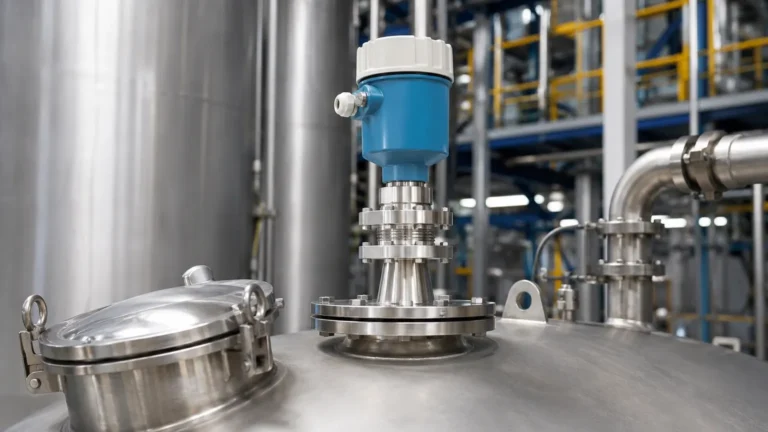
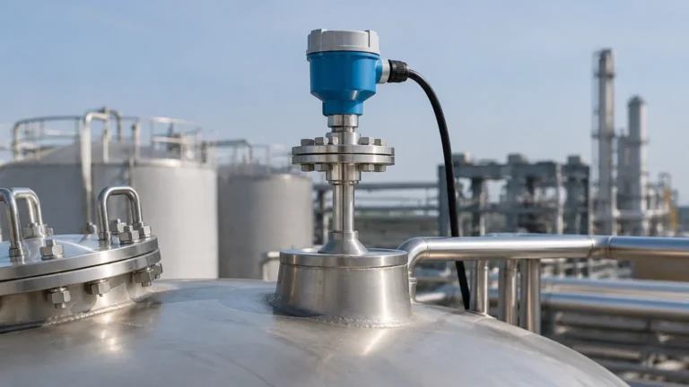
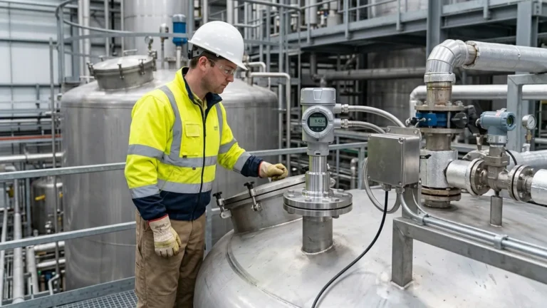
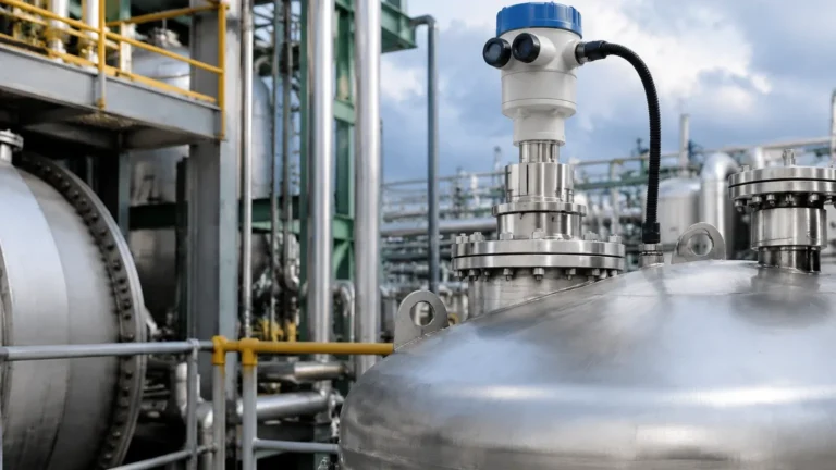
Radar Level Transmitter Stilling Well
Radar Level Transmitter Stilling Well: An Engineering Guide to Application and Selection
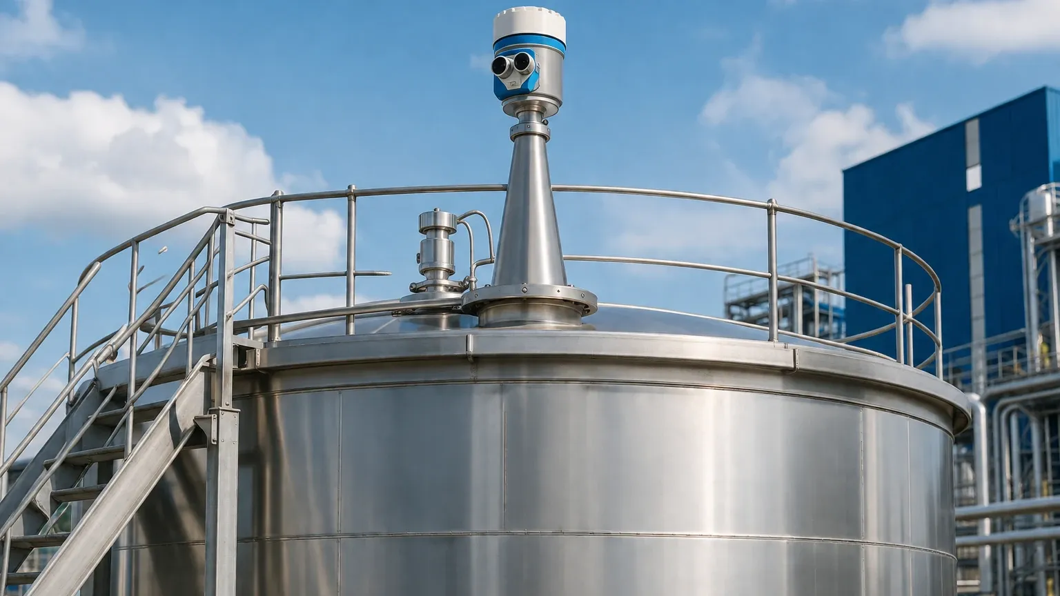
In industrial process control, achieving accurate and stable level measurement is often challenged by surface turbulence, foam, and internal tank obstructions. For many engineers, the integration of a radar level transmitter stilling well is the standard solution to these environmental interferences. By providing a controlled environment for electromagnetic wave propagation, stilling wells allow Radar Level Meters to deliver high-precision data even in the most demanding reactor or storage vessel conditions.
This guide examines the technical principles, selection criteria, and installation requirements for using stilling wells with radar level technology, providing a factual framework for B2B procurement and system design.
1. Measurement Principles in a Stilling Well
To understand why a stilling well is used, one must first understand how radar level measurement functions. Radar instruments operate on the Time-of-Flight (ToF) principle. The sensor emits a high-frequency electromagnetic pulse (typically in the 6GHz, 26GHz, or 80GHz range) that travels to the product surface, reflects, and returns to the receiver. The distance is calculated based on the time elapsed and the speed of light.
The Waveguide Effect
When a radar transmitter is mounted on a stilling well (a vertical pipe submerged in the liquid), the pipe acts as a waveguide. Instead of the radar signal spreading in a conical beam as it would in open space, the electromagnetic waves are confined within the internal diameter of the pipe.
This confinement offers several physical advantages:
- Signal Concentration: The energy of the pulse is focused, which is particularly beneficial for liquids with a low dielectric constant (low reflectivity).
- Echo Isolation: The pipe wall acts as a shield, preventing the radar from "seeing" agitators, baffles, or heating coils located elsewhere in the tank.
- Surface Stabilization: The liquid inside the pipe remains calm even if the main body of liquid is turbulent due to mixing or high-velocity inflow.
2. When to Use a Radar Level Transmitter Stilling Well
While modern 80GHz radar units have narrow beam angles that can often bypass obstructions, a stilling well remains necessary in specific industrial scenarios:
Turbulence and Agitation
In chemical reactors where high-speed mixers create vortices or significant surface ripples, the radar signal can be scattered, leading to a loss of echo. The stilling well provides a bypass area where the liquid level represents the tank average without the surface noise.
Low Dielectric Liquids
Hydrocarbons and solvents often have low dielectric constants (εr < 2.0). In an open tank, the reflection from these surfaces is weak. By using a stilling well, the radar energy is concentrated, significantly increasing the amplitude of the return signal.
Heavy Foam Layers
Foam can absorb radar signals, leading to false readings or signal loss. A stilling well allows the liquid to enter from the bottom or through side perforations, often leaving the foam layer outside the pipe, thereby allowing the radar to measure the true liquid surface.
Internal Obstructions
In older tanks or complex vessels with extensive internal bracing, a stilling well provides a clear, unobstructed path for the signal from the top to the bottom of the vessel.
3. Technical Selection Criteria
Selecting the correct radar level transmitter stilling well requires careful consideration of pipe geometry, material, and the nature of the medium.
Pipe Diameter and Schedule
Common diameters range from 50mm (2") to 300mm (12"). The choice depends on the radar's frequency and antenna type.
- Small Diameters (50mm – 80mm): Suitable for high-frequency (80GHz) radars or guided wave radar (GWR) coaxial probes.
- Large Diameters (100mm – 200mm): Standard for 26GHz pulse radar or FMCW (Frequency Modulated Continuous Wave) systems. Larger pipes are easier to clean and less prone to clogging.
Material Compatibility
Welk provides level measurement solutions across various industries, requiring materials that withstand corrosive environments.
- 316L Stainless Steel: The industry standard for chemical and water treatment applications.
- Carbon Steel: Used in oil and gas for non-corrosive hydrocarbons.
- Plastic (PVC/CPVC/PTFE): Used for highly aggressive acids where metallic contact must be avoided.
Venting and Equalization Holes
For the level inside the pipe to match the level outside, the stilling well must be properly vented.
1. Pressure Equalization: A vent hole must exist at the top of the pipe (above the maximum liquid level) to prevent a vacuum or pressure build-up that would depress the liquid level inside the pipe.
2. Liquid Flow: Perforations or slots along the length of the pipe allow the liquid to flow in and out. These holes must be sized to prevent clogging while remaining small enough to keep the internal surface calm.
| Feature | Recommendation | Engineering Reason |
| :— | :— | :— |
| Hole Diameter | 6mm to 13mm (1/4" to 1/2") | Balances flow rate with signal integrity. |
| Hole Spacing | Every 150mm to 300mm | Ensures rapid response to level changes. |
| Internal Finish | Smooth, burr-free | Prevents false echoes from weld beads or metal burrs. |
| Bottom Design | Open or with 45° cut | Prevents sediment build-up at the base. |
4. Installation Considerations and Best Practices
The performance of a radar level transmitter stilling well is highly dependent on the quality of installation. Minor deviations can lead to significant measurement errors.
Vertical Alignment
The pipe must be installed as vertically as possible. A deviation of more than 0.5 to 1 degree can cause the radar signal to hit the pipe wall repeatedly, leading to signal attenuation and increased "ringing" (noise) near the top of the sensor.
Weld Quality
Internal welds must be ground smooth. Any protrusion inside the pipe, such as a weld bead or a misaligned flange, will create a static reflection. The radar may lock onto this reflection instead of the liquid level, especially when the tank is nearly empty.
The "Dead Zone" and Standoffs
Every radar has a near-field dead zone (typically 50mm to 300mm). If the stilling well is mounted via a tall nozzle, ensure the antenna extends into the pipe or that the nozzle diameter matches the pipe diameter to minimize signal interference at the top of the range.
Venting Location
Ensure the vent hole is not located where it can be blocked by the mounting flange or the radar antenna itself. Air must be able to move freely between the tank headspace and the stilling well interior.
5. Limitations and Risks
While effective, stilling wells are not a universal solution. Engineers should be aware of the following limitations:
- Viscous and Sticky Liquids: High-viscosity fluids or liquids that crystallize can coat the inside of the pipe. This coating can cause the radar signal to slow down (changing the measured distance) or create false echoes. In such cases, non-contact radar in an open tank or a large-diameter bypass chamber is preferred.
- Clogging of Equalization Holes: In wastewater or slurries, solids can plug the holes, causing the level inside the pipe to lag behind the actual tank level. This creates a dangerous situation where the transmitter reports a safe level while the tank is overfilling.
- Dielectric Shifts: If the liquid is a mixture that separates (like oil and water), the stilling well may capture a non-representative sample if the holes are not positioned correctly.
6. Buyer’s Checklist: Confirming Specifications
When sourcing a radar level transmitter and its associated stilling well for international projects, B2B buyers should confirm the following data points with the manufacturer:
1. Radar Frequency: Is the transmitter 26GHz or 80GHz? (Higher frequencies generally perform better in smaller pipes).
2. Pipe Schedule: Is the internal diameter consistent? (Schedule 40 is standard; Schedule 80 has a smaller ID which may affect antenna fit).
3. Process Connections: Does the stilling well flange match the radar's mounting flange (e.g., ANSI, DIN, or JIS standards)?
4. Surface Treatment: Is the internal pipe surface passivated or polished for food-grade or high-purity chemical applications?
5. Integration: Does the radar software include a "Stilling Well Mode"? This software setting adjusts the pulse processing to account for the waveguide effect.
7. Frequently Asked Questions (FAQ)
Q: Can I use a stilling well with a Guided Wave Radar (GWR)?
A: Yes. While GWR uses a physical probe, placing it inside a stilling well (often called a coaxial chamber in this context) provides the highest possible signal-to-noise ratio and protects the probe from mechanical damage in agitated tanks.
Q: How do I clean a stilling well?
A: For tanks that require frequent cleaning, stilling wells should be designed with a removable top flange or a flushing port. In some industries, the pipe is designed to be pulled out of the tank for manual cleaning.
Q: Does the material of the pipe affect the radar signal?
A: Metal pipes (Stainless Steel, Carbon Steel) act as excellent waveguides. Plastic pipes do not reflect radar waves in the same way; when using plastic, the radar effectively "sees through" the pipe unless the pipe is specifically used as a mechanical stabilizer for a GWR probe.
Q: What is the maximum length for a stilling well?
A: Technically, there is no strict limit, provided the pipe is straight and vertical. Stilling wells have been successfully implemented in deep wells and large oil storage tanks exceeding 20 meters in height.
Conclusion
A radar level transmitter stilling well is a critical component for ensuring reliability in complex industrial environments. By stabilizing the liquid surface and shielding the signal from interference, it allows Radar Level Meters to perform at their theoretical limits of accuracy. When designed with proper venting, material compatibility, and smooth internal geometry, the stilling well transforms a challenging measurement task into a predictable and maintainable process control point. For engineers and B2B buyers, focusing on these factual engineering boundaries ensures long-term operational success and safety in level monitoring applications.