Radar Level Indicator Transmitter
Radar Level Indicator Transmitter: A Comprehensive Engineering Guide to Non-Contact Measurement
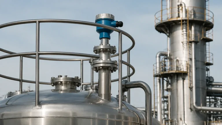
In modern industrial process control, the requirement for precise, reliable, and maintenance-free level monitoring has led to the widespread adoption of radar technology. A radar level indicator transmitter serves a dual purpose: it provides a real-time local visual representation of the vessel level (indicator) while simultaneously converting that physical measurement into an electronic signal (transmitter) for remote monitoring and control systems.
This guide examines the fundamental measurement principles, selection parameters, and installation requirements necessary for engineers and procurement professionals to implement these instruments effectively across various industrial sectors.
Measurement Principles of Radar Technology
Before selecting a radar level indicator transmitter, it is essential to understand the two primary methods used to calculate distance: Pulse Radar and Frequency Modulated Continuous Wave (FMCW).
1. Pulse Radar (Time-of-Flight)
Pulse radar instruments emit short microwave pulses toward the surface of the medium. These pulses travel at the speed of light, reflect off the surface, and return to the sensor antenna. The instrument measures the time elapsed between emission and reception—the "Time-of-Flight" (ToF). Since the speed of light is constant, the distance is calculated using the formula:
*Distance = (Speed of Light × Time) / 2*
Pulse radar is generally preferred for its lower power consumption and suitability for simple liquid applications.
2. Frequency Modulated Continuous Wave (FMCW)
FMCW radar emits a continuous signal with a constantly changing frequency (a frequency sweep). When the reflected signal is received, it is compared with the frequency being emitted at that exact moment. The difference in frequency (the "beat frequency") is directly proportional to the distance.
FMCW technology, particularly at higher frequencies like 80 GHz, offers superior resolution and accuracy. It is highly effective in complex environments involving heavy dust, steam, or narrow tanks where signal interference is a concern.
The Role of Frequency: 26 GHz vs. 80 GHz
The operating frequency of a Radar Level Meters significantly impacts its performance in industrial environments.
* 26 GHz (K-band): This is the traditional standard for many industrial applications. It offers a balance between beam focus and the ability to penetrate some foam or vapor. It is widely used in medium-sized tanks for both liquids and solids.
* 80 GHz (W-band): The higher frequency allows for a much narrower beam angle (often as small as 3°). This precision makes it ideal for tall, narrow silos or tanks with internal obstructions like agitators or heating coils. It also provides better reflection on low-dielectric materials.
Selection Criteria for Industrial Applications
Choosing the correct radar level indicator transmitter requires an analysis of the process media and the environment. The following factors are critical:
Dielectric Constant (εr)
Radar waves rely on a change in the dielectric constant at the surface of the medium to reflect the signal.
* High εr (>10): Materials like water or acids reflect signals strongly, making them easy to measure.
* Low εr (1.4 to 4): Materials like hydrocarbons, oils, or plastic pellets reflect very little energy. In these cases, high-sensitivity FMCW radar or Guided Wave Radar (GWR) is required.
Process Conditions
* Temperature and Pressure: Standard sensors typically handle up to 150°C and 4 MPa (40 bar). However, specialized high-temperature versions can withstand up to 450°C using ceramic seals and cooling fins.
* Chemical Compatibility: The wetted parts (antenna and flange) must be compatible with the media. Common materials include 316L Stainless Steel, PTFE (Teflon), and PP (Polypropylene).
* Turbulence and Foam: Heavy surface foam can absorb radar signals. In such instances, lower frequency radar or guided wave technology may be more reliable.
Selection Comparison Table
| Feature | 26 GHz Pulse Radar | 80 GHz FMCW Radar | Guided Wave Radar (GWR) |
| :— | :— | :— | :— |
| Best Use Case | Large liquid tanks | Narrow silos, solids | Low dielectric oils, small tanks |
| Beam Angle | 8° – 20° | 3° – 8° | N/A (signal follows probe) |
| Accuracy | ±3 mm to ±5 mm | ±1 mm | ±2 mm |
| Max Range | Up to 30 m | Up to 120 m | Up to 30 m |
| Dust/Vapor Resistance | Moderate | High | Excellent |
| Installation | Top-mounted, non-contact | Top-mounted, non-contact | Contacting (probe in media) |
Installation Considerations and Constraints
Proper installation is the most significant factor in ensuring the long-term accuracy of a radar level indicator transmitter. Engineers should adhere to the following guidelines:
1. Nozzle Height and Diameter: The antenna should ideally extend slightly beyond the bottom of the mounting nozzle to prevent signal interference from the nozzle edge. If the nozzle is very long, a stand-off pipe or a specific antenna extension may be required.
2. Avoid the "Dead Zone": Every radar sensor has a minimum measurable distance (blocking distance) near the antenna, typically 0.1 m to 0.5 m. The maximum liquid level should never enter this zone.
3. Obstruction Clearance: The radar beam spreads as it travels. Ensure the "signal cone" does not intersect with tank walls, ladders, or agitators. If an agitator is present, software-based "false echo suppression" can be used to ignore the reflection from the blades.
4. Positioning: Do not install the sensor in the center of a domed tank, as this can cause multiple reflections that confuse the transmitter. Ideally, the sensor should be placed at 1/4 to 1/3 of the tank diameter from the wall.
5. Inlet Interference: Never install the radar directly above the filling inlet. The falling stream of material will cause significant signal noise and erratic readings.

Limitations and Application Risks
While radar is highly versatile, it is not a "one-size-fits-all" solution. Awareness of the following risks is vital:
* Heavy Foam: Some types of dense, thick foam (like those found in wastewater treatment or chemical fermentation) can completely absorb a high-frequency radar signal, resulting in a "loss of echo" error.
* Vacuum Conditions: While radar works in a vacuum, the sealing of the instrument must be rated for vacuum service to prevent air leakage into the process or damage to the electronics.
* Condensation: Heavy condensation on the antenna can attenuate the signal. Selecting an antenna with a convex PTFE drip-off cover can help mitigate this by allowing droplets to run off the face of the sensor.
The "Indicator" and "Transmitter" Functions
In a B2B industrial context, the integration of the device into the wider control architecture is paramount.
* The Indicator: Most modern units feature an integrated backlit LCD. This allows field technicians to verify levels locally without needing to check the control room. It also facilitates local configuration via push-buttons or magnetic keys (for explosion-proof environments).
* The Transmitter: The device typically outputs a 4-20 mA signal with HART protocol. This allows for digital communication over the analog loop, providing diagnostic data and multi-variable reporting. For advanced automation, RS485 (Modbus) or Profibus PA/DP options are often available.
Frequently Asked Questions (FAQ)
Q: Can a radar level indicator transmitter measure solids like cement or grain?
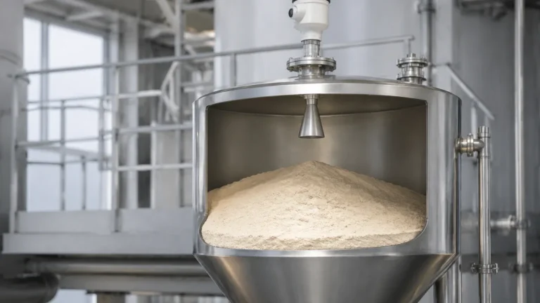
A: Yes. However, solids often have an angle of repose (a sloped surface). 80 GHz FMCW radar is recommended for solids because its narrow beam can better handle the uneven surface and the dusty environment typical of silos.
Q: Is radar better than ultrasonic level sensors?
A: Generally, yes. Ultrasonic sensors rely on sound waves, which are affected by air temperature, pressure, and vapor composition. Radar uses electromagnetic waves, which are unaffected by these atmospheric changes, making radar much more stable in industrial processes.
Q: How do I maintain a radar transmitter?
A: Radar is virtually maintenance-free because it has no moving parts and is non-contact. The only common maintenance task is checking the antenna for heavy buildup or scaling, which may need to be cleaned periodically if the media is particularly sticky.
Q: What information should I provide when requesting a quote?
A: To ensure the correct configuration, provide:
1. Media name and dielectric constant.
2. Tank height and required measurement range.
3. Process temperature and pressure.
4. Connection type (flange size or thread).
5. Presence of any internal obstructions or agitators.
Conclusion
The implementation of a radar level indicator transmitter represents a significant upgrade in process reliability for any industrial facility. By understanding the dielectric properties of the media and the geometric constraints of the vessel, engineers can select a frequency and antenna type that minimizes signal loss and maximizes accuracy. Whether managing water treatment facilities, chemical storage, or oil and gas processing, radar technology remains the gold standard for non-contact level measurement.