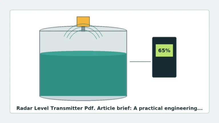
Radar Level Transmitter Manual PDF
In the landscape of industrial automation, precise level measurement is a cornerstone of process safety and efficiency. Among the various technologies available, non-contact radar measurement has emerged as a gold standard for challenging environments involving corrosive chemicals, high temperatures, and varying pressures. For engineers and procurement specialists, the technical documentation, often searched for as a radar level transmitter manual pdf, serves as the definitive reference for ensuring the device is correctly specified, installed, and maintained.
This article provides a comprehensive technical overview of radar level measurement, detail selection criteria, and the essential information found in technical manuals to support successful deployment in industrial applications.
Measurement Principles of Radar Level Meters
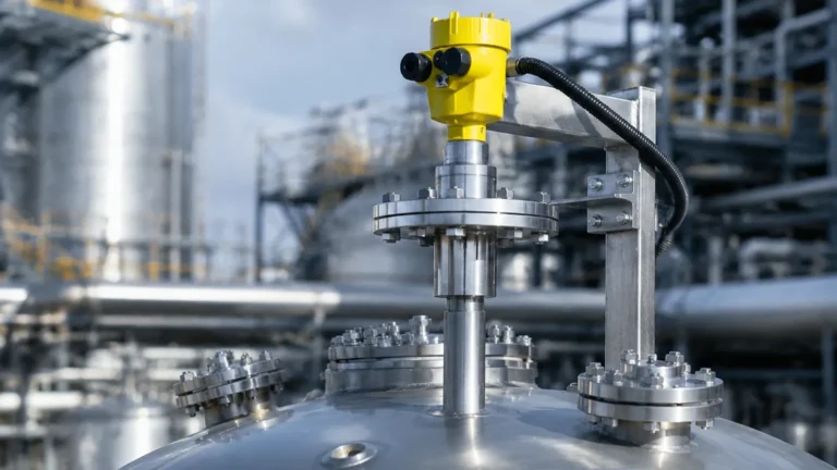
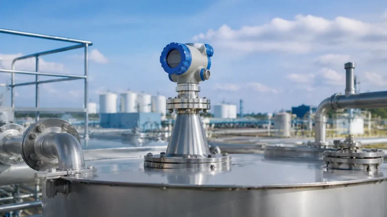
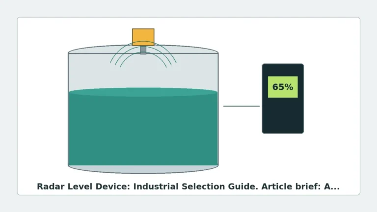
Radar level transmitters operate by emitting electromagnetic waves (microwaves) toward the surface of the medium being measured. These waves travel at the speed of light. When they encounter a change in the dielectric constant (the boundary between air and the product), a portion of the energy is reflected back to the sensor. The instrument then calculates the distance based on the properties of the returned signal.
There are two primary methods used in modern Radar Level Meters:
1. Pulse Radar (Time of Flight)
Pulse radar transmitters emit short microwave pulses. The device measures the time it takes for the pulse to travel to the surface and back. This "Time of Flight" (ToF) is directly proportional to the distance. While historically popular due to lower power consumption, pulse radar is increasingly being superseded by FMCW technology in high-precision applications.
2. Frequency Modulated Continuous Wave (FMCW)
FMCW radar transmits a continuous signal with a constantly changing frequency (a frequency sweep). The reflected signal is received and compared to the signal being transmitted at that exact moment. The difference in frequency between the transmitted and received signals is proportional to the distance to the product surface. FMCW offers significantly higher resolution and signal-to-noise ratios, making it ideal for measuring liquids with low reflectivity or in tanks with internal obstructions.
Understanding Frequency: 26GHz vs. 80GHz
When reviewing a radar level transmitter manual pdf, one of the most critical specifications is the operating frequency. The frequency determines the beam angle and the instrument's ability to handle foam, dust, or narrow nozzles.
* 26GHz Radar: Often referred to as "high frequency" in older contexts, 26GHz is a versatile choice for many liquid applications. It offers a balance between signal strength and cost. However, it typically has a wider beam angle (approximately 8° to 12°), which requires more clearance from tank walls and internal structures like agitators.
* 80GHz Radar: This represents the current state-of-the-art. The higher frequency allows for a much narrower beam angle (as low as 3°). This precision makes it possible to measure in tall, narrow silos or tanks with complex internal geometry without interference from the walls or equipment. Furthermore, 80GHz sensors are often more compact, allowing for installation on smaller process connections.
Technical Selection Criteria
Selecting the correct radar level transmitter requires a thorough analysis of the process conditions. The following table summarizes the key factors that influence selection:
| Factor | Impact on Selection | Engineering Consideration |
| :— | :— | :— |
| Dielectric Constant ($ε_r$) | Reflectivity | Materials with $ε_r < 1.4$ (e.g., liquid gases) require high-sensitivity FMCW or guided wave radar. |
| Process Temperature | Sensor Housing/Antenna | Standard units handle up to 80°C; specialized high-temp versions reach 250°C or higher. |
| Process Pressure | Flange/Seal Rating | Standard atmospheric up to 40 bar (4.0 MPa). High-pressure variants are required for boilers. |
| Medium State | Antenna Type | Liquids often use horn or lens antennas; solids/powders require parabolic or dust-resistant lens antennas. |
| Vessel Geometry | Beam Angle | Narrow tanks or those with agitators require 80GHz radar to avoid false echoes. |
Essential Components of a Radar Level Transmitter Manual PDF
An authoritative technical manual is not merely an instruction booklet; it is a vital engineering document. When evaluating a radar level transmitter manual pdf, ensure it contains the following sections:
Wiring and Electrical Interface
Industrial radar units typically utilize a 2-wire 4-20mA loop-powered configuration, often with HART (Highway Addressable Remote Transducer) protocol for digital communication. The manual must provide clear wiring diagrams, including grounding requirements and shielding instructions to prevent Electromagnetic Interference (EMI).
Configuration and Parameterization
Modern transmitters allow for the setting of "Near-end Blanking" (to ignore signals very close to the antenna) and "False Echo Suppression." The manual should detail how to map the tank profile to ignore fixed obstructions like ladders or heating coils.
Error Codes and Diagnostics
In the event of signal loss or hardware failure, the manual’s troubleshooting section is indispensable. It should define standard error codes (e.g., NE43 compliant signal levels) and provide a step-by-step guide to resolving "Lost Echo" or "Signal Weak" alarms.
Installation Considerations and Best Practices
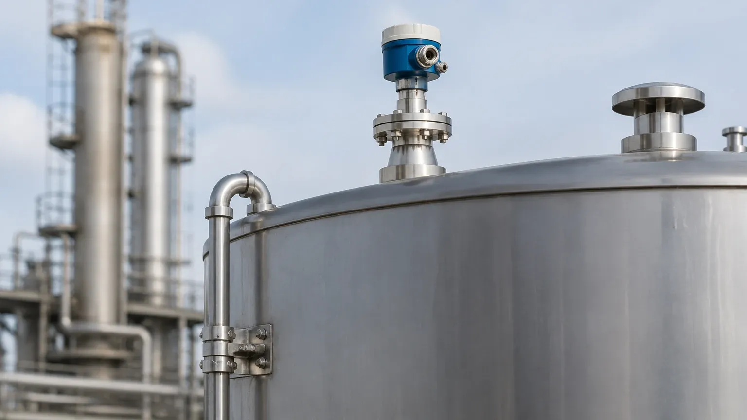
Correct installation is the most significant factor in the long-term reliability of a radar level meter. Even the most advanced 80GHz sensor will fail if installed incorrectly.
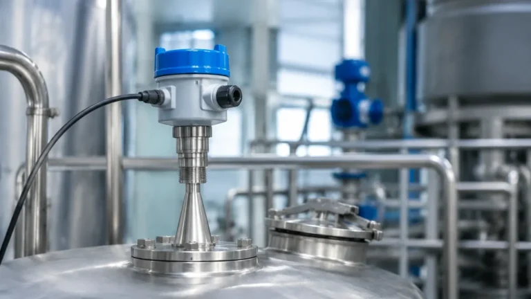
1. Nozzle Height and Diameter: The antenna should ideally extend slightly beyond the bottom of the mounting nozzle to prevent signal ringing within the nozzle itself. If the nozzle is very long, a horn extension may be necessary.
2. Wall Distance: To avoid "multipath" reflections, the sensor should be mounted at a distance from the tank wall, typically at least 1/6th of the tank diameter.
3. Avoiding the Center: In cylindrical tanks with torispherical or conical bottoms, do not mount the sensor in the exact center. This prevents the "parabolic effect," where the tank bottom focuses multiple reflections back to the sensor, causing signal saturation or errors when the tank is nearly empty.
4. Obstruction Clearance: Ensure the radar beam path is clear of filling streams, agitator blades, and limit switches. If an obstruction is unavoidable, the software's false echo mapping must be used during commissioning.
5. Environmental Protection: While many industrial radar meters are rated IP66 or IP67, a sunshade is recommended for outdoor installations to prevent extreme temperature fluctuations from affecting the internal electronics.
Limitations and Application Risks
While radar is highly versatile, it is not a universal solution. Engineers must be aware of the following limitations:
* Heavy Foam: Dense, thick foam can absorb the radar signal entirely, leading to a "lost echo" condition. In such cases, a magnetic level gauge or a guided wave radar (GWR) may be more appropriate.
* Vacuum Conditions: While radar works in a vacuum, the sealing of the antenna becomes a critical failure point. Ensure the manual specifies the vacuum rating of the process seal.
* Extremely Low Dielectric Media: If the product has a very low dielectric constant, the signal may pass through the product and reflect off the tank bottom instead. This requires advanced "Bottom Echo Tracking" software or the use of a stilling well.
* Condensation and Buildup: Significant moisture or product buildup on the antenna can attenuate the signal. For these applications, antennas with a PTFE (Teflon) or PEEK lens are preferred as they offer non-stick properties.
Frequently Asked Questions (FAQ)
Q: Can a radar level transmitter measure through a plastic tank lid?
A: Yes, because plastic has a low dielectric constant, microwaves can penetrate the lid. This allows for non-invasive measurement without cutting a hole in the tank, provided the plastic is not carbon-filled or metallic-coated.
Q: What is the difference between "Non-Contact Radar" and "Guided Wave Radar"?
A: Non-contact radar sends waves through the air. Guided Wave Radar (GWR) sends the pulse down a physical probe (cable or rod). GWR is better for low-dielectric liquids and applications with heavy foam or turbulence, while non-contact radar is better for corrosive or hygienic applications where touching the media is undesirable.
Q: How often does a radar level meter need calibration?
A: Because radar has no moving parts and the speed of light is constant, the "zero" and "span" do not drift like hydrostatic pressure sensors. However, annual verification is recommended in regulated industries (e.g., pharmaceutical or food) to ensure the electronics are functioning within specified accuracy limits.
Q: Does the presence of dust affect the measurement?
A: Generally, no. Radar waves are much longer than dust particles, allowing them to pass through heavy dust clouds that would blind an ultrasonic or laser sensor. This makes radar the preferred choice for grain silos and cement plants.
Conclusion
The successful implementation of radar technology depends on a deep understanding of the process environment and adherence to technical guidelines. By consulting the radar level transmitter manual pdf for specific device limits and following rigorous installation standards, industrial operators can achieve maintenance-free level measurement for years. For high-accuracy requirements or complex tank geometries, 80GHz FMCW technology remains the most robust choice in the modern industrial market.