Radar Level Transmitter Working Principle Animation
Radar Level Transmitter Working Principle Animation: A Technical Guide to Non-Contact Measurement
In the realm of industrial process control, the ability to accurately monitor liquid and solid levels without physical contact is a significant engineering advantage. Radar Level Meters have become the industry standard for challenging environments where temperature, pressure, and corrosive properties make traditional sensors impractical. Understanding the radar level transmitter working principle animation—conceptually visualizing how electromagnetic waves interact with surfaces—is essential for engineers tasked with selecting and maintaining these instruments.
This article provides a deep dive into the physics, hardware configurations, and practical installation requirements for radar level measurement technology, serving as a reference for B2B procurement and plant engineering teams.
1. The Core Measurement Principles
Radar level transmitters operate on the principle of "Time of Flight" (ToF). They emit high-frequency electromagnetic pulses or continuous waves that travel at the speed of light. When these waves encounter a medium with a different dielectric constant ($ε_r$) than the atmosphere (usually air or vacuum), a portion of the energy is reflected back to the sensor.
Pulse Radar Technology
Pulse radar instruments emit short microwave bursts and then switch to a receiving mode to listen for the return echo. The distance ($D$) is calculated using the formula:
$$D = \frac{c \times t}{2}$$
Where:
* c is the speed of light (~300,000 km/s).
* t is the measured time between emission and reception.
FMCW (Frequency Modulated Continuous Wave)
Modern high-precision radar transmitters often utilize FMCW. Instead of pulses, the device emits a continuous signal with a frequency that changes linearly over time (a frequency sweep). The reflected signal is received and mixed with the currently emitted signal. The difference in frequency between the transmitted and received signals is directly proportional to the distance. This method typically offers higher accuracy and better signal-to-noise ratios in complex industrial tanks.
2. Visualizing the Process: Radar Level Transmitter Working Principle Animation
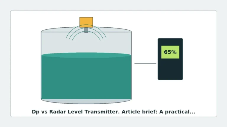
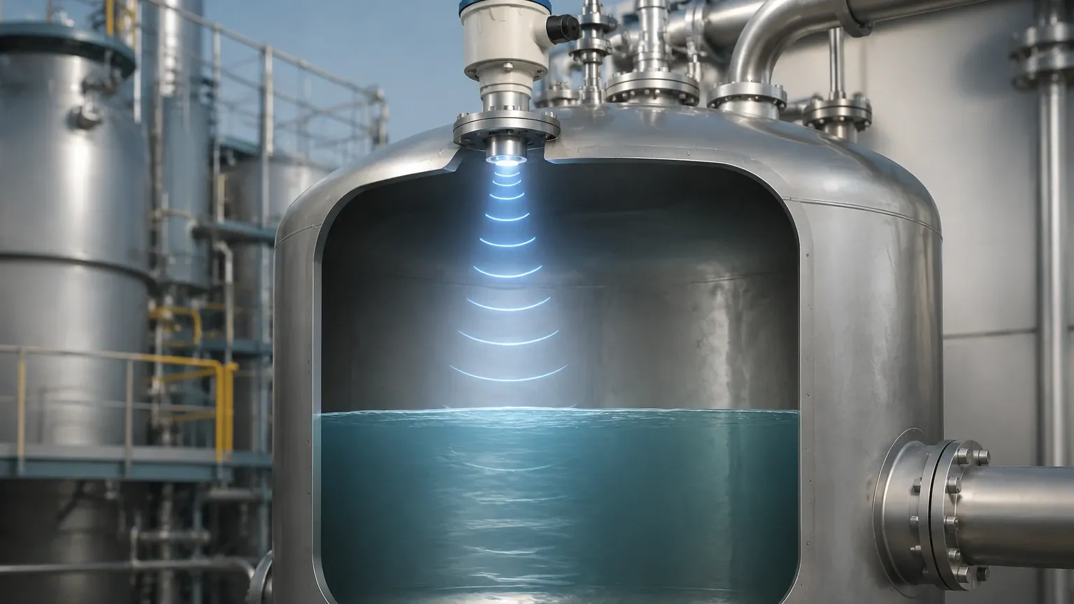
When engineers refer to a radar level transmitter working principle animation, they are looking for a visualization of how the wave behaves within a vessel. In a typical animation, you would observe:
1. Emission: A narrow beam of microwaves travels downward from the antenna.
2. Interaction: Upon hitting the material surface (liquid or solid), the waves scatter. The strength of the return signal depends on the Dielectric Constant ($ε_r$) of the material. Water ($ε_r ≈ 80$) reflects very strongly, while hydrocarbons like oil ($ε_r ≈ 2$) reflect much more weakly.
3. Echo Filtering: The animation would show the "echo curve," where the transmitter distinguishes the true level from false reflections caused by agitators, heating coils, or tank walls.
3. Frequency Selection: 6GHz, 26GHz, and 80GHz
The frequency of the radar signal determines the beam angle, the size of the antenna, and the ability of the signal to penetrate dust or foam.
| Frequency | Beam Angle | Typical Applications | Strengths |
| :— | :— | :— | :— |
| 6 GHz (C-Band) | Wide (approx. 20°-30°) | Large vessels with heavy turbulence or steam. | High penetration through foam and steam. |
| 26 GHz (K-Band) | Medium (approx. 8°-12°) | General purpose liquid and solid storage. | Balanced performance for most industrial tanks. |
| 80 GHz (W-Band) | Narrow (approx. 3°-4°) | Small tanks, narrow nozzles, and high-precision solids. | Excellent focusing; avoids internal obstructions easily. |
4. Hardware and Antenna Design
The antenna is the interface between the transmitter electronics and the process environment. Choosing the right antenna is as critical as choosing the correct frequency.
* Horn Antennas: The most common design for 26GHz units. They are robust and suitable for various liquids. They can be manufactured from stainless steel or coated with PTFE for corrosive environments.
* Lens Antennas: Typically used in 80GHz radar level meters. The lens allows for a very flush design, which is ideal for hygienic applications or where buildup on the antenna is a concern.
* Rod Antennas: Often used in smaller openings or for corrosive chemicals where a full PTFE rod is required to protect the sensor.
* Parabolic Antennas: Used for long-range measurement of solids in large silos, providing a large surface area to capture weak reflections from uneven material surfaces.
5. Engineering Installation Considerations
A radar level transmitter is only as accurate as its installation. Because the waves travel in a cone-shaped beam, physical obstructions within that cone will create false echoes.
Nozzle Dimensions
The mounting nozzle should be as short as possible. If the nozzle is too long or too narrow, the radar signal may reflect off the bottom edge of the nozzle, creating a "ringing" effect that masks the signal from the actual product level. For 80GHz radars, this is less of a concern due to the narrow beam, but for 6GHz and 26GHz units, the nozzle height-to-diameter ratio must be strictly monitored.
Obstructions and False Echo Suppression
Internal tank structures like ladders, agitator blades, and spray balls are common. Most modern Radar Level Meters include a software feature called "False Echo Suppression" or "Background Subtraction." During commissioning, the engineer records the echo profile of an empty tank. The transmitter then "learns" which reflections are static obstructions and ignores them during operation.
Positioning
* Avoid the Center: Do not install the transmitter in the exact center of a domed-roof tank, as this can focus multiple reflections back to the sensor, causing signal interference.
* Avoid the Feed Stream: Never install the sensor directly above the point where the product enters the tank, as the turbulence and falling material will interfere with the signal.
* Distance from Wall: Maintain a minimum distance from the tank wall (typically 200mm to 500mm depending on the beam angle) to prevent side-lobe reflections.
6. Limitations and Application Risks
While radar is highly versatile, it is not a "one-size-fits-all" solution. Engineers must account for the following risks:
1. Heavy Foam: Depending on the density and conductivity of the foam, the radar signal may reflect off the top of the foam, pass through it to the liquid, or be completely absorbed. 6GHz radar is generally better at penetrating foam than 80GHz.
2. Extremely Low Dielectric Materials: For materials with $ε_r < 1.4$ (such as some liquefied gases), the reflection may be too weak for standard non-contact radar. In these cases, Guided Wave Radar (GWR) is often preferred.
3. Vacuum and High Pressure: While the speed of light is constant in a vacuum, extremely high-pressure gases can slightly change the propagation speed of the wave, requiring a correction factor in high-precision applications.
7. International Buyer’s Checklist
When sourcing radar level transmitters for global industrial projects, procurement teams should confirm the following technical specifications with the manufacturer:
* Process Connection: Ensure compatibility with local standards (e.g., Flange DIN DN80 vs. ANSI 3").
* Output Protocol: Is the system 4-20mA HART, Modbus RTU, or Profibus? Most modern plants require HART for remote configuration.
* Certifications: Verify ATEX/IECEx for hazardous areas, or SIL2/SIL3 ratings if the device is part of a Safety Instrumented System (SIS).
* Material Compatibility: Confirm that the wetted parts (antenna and seals) are compatible with the process media (e.g., Hastelloy C for aggressive acids).
8. Frequently Asked Questions (FAQ)
Q: Can radar level meters measure through a plastic tank roof?
A: Yes. Because plastic has a low dielectric constant, high-frequency radar signals can often pass through the top of a plastic or fiberglass tank, allowing for measurement without cutting a hole in the vessel. This is common in chemical IBC (Intermediate Bulk Container) monitoring.
Q: How does dust affect the measurement in solids silos?
A: Unlike ultrasonic sensors, which are easily blocked by dust, radar waves are largely unaffected by air-borne particulates. However, heavy dust buildup on the antenna itself can attenuate the signal. Using a lens antenna or a dust-purging system (compressed air) can mitigate this.
Q: What is the "Dead Zone"?
A: The dead zone (or blocking distance) is the area immediately below the antenna where the transmitter cannot accurately measure. This is usually between 50mm and 200mm. If the liquid level enters this zone, the reading may become erratic.
Conclusion
Understanding the radar level transmitter working principle animation and the underlying physics of electromagnetic wave propagation allows engineers to deploy these instruments with confidence. By selecting the appropriate frequency, antenna design, and installation location, industrial facilities can achieve reliable, maintenance-free level measurement in even the most demanding environments. For complex applications, consulting with a specialized manufacturer like Welk ensures that the selected Radar Level Meters are optimized for the specific dielectric properties and physical constraints of the process.
Download Radar Level Transmitter Working Principle Animation as a PDF