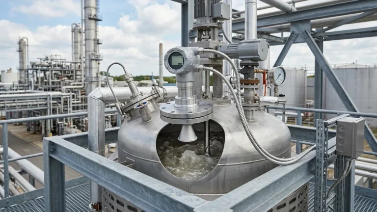
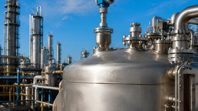
Radar Level Transmitter Yokogawa
Radar Level Transmitter Yokogawa: An Engineering Guide to High-Precision Level Measurement
In the landscape of industrial automation, the ability to accurately monitor liquid and solid levels within process vessels is critical for safety, efficiency, and inventory management. Among the various technologies available, non-contact radar measurement has emerged as a gold standard for challenging environments. A radar level transmitter Yokogawa represents a high-tier solution in this category, often utilized in oil and gas, chemical processing, and power generation.
This guide explores the underlying principles of radar technology, the specific engineering considerations for selecting and installing these instruments, and how they integrate into broader industrial systems. For those seeking a wider range of high-performance instrumentation, exploring Radar Level Meters provides a comprehensive view of the technology available to meet diverse process requirements.
1. Understanding Radar Measurement Principles
Before selecting a specific instrument like a radar level transmitter Yokogawa, it is essential to understand the two primary methods used in radar level detection: Pulse Radar and Frequency Modulated Continuous Wave (FMCW).
Pulse Radar Technology
Pulse radar instruments emit a microwave signal toward the product surface in short, timed bursts. The instrument measures the "Time of Flight" (ToF)—the duration it takes for the pulse to travel to the surface and return to the sensor. Because the speed of light is constant, the distance is calculated as:
\[ Distance = \frac{C \times t}{2} \]
Where *C* is the speed of light and *t* is the transit time. Pulse radar is generally known for its lower power consumption, making it suitable for loop-powered (2-wire) installations.
FMCW (Frequency Modulated Continuous Wave)
FMCW radar, which is frequently utilized in high-end transmitters, emits a continuous signal with a constantly changing frequency. The reflection from the product surface is received and compared against the signal being emitted at that exact moment. The frequency difference between the transmitted and received signals is directly proportional to the distance. FMCW radar typically offers higher accuracy and a better signal-to-noise ratio than pulse radar, making it ideal for applications with turbulence or low dielectric constants.
2. Key Features of Radar Level Transmitter Yokogawa Series
Yokogawa’s approach to radar measurement, particularly in their Pulsar and LR series, focuses on reliability in extreme conditions. These transmitters are engineered to handle high pressures and temperatures while maintaining signal integrity.
Advanced Signal Processing
One of the defining characteristics of a radar level transmitter Yokogawa is its ability to filter out "false echoes." In many industrial tanks, internal structures like agitators, heating coils, and ladders can create reflections that mimic the product surface. Advanced algorithms allow the transmitter to map the tank’s interior and ignore these static reflections, focusing solely on the dynamic level of the medium.
Frequency Options
Radar transmitters operate at different frequencies, typically ranging from 6 GHz to 80 GHz.
- Low Frequency (approx. 6 GHz): Better suited for applications with heavy foam, dust, or vapor, as the longer wavelength can penetrate these obstacles.
- High Frequency (approx. 80 GHz): Offers a much narrower beam angle, which is essential for tall, narrow tanks or vessels with many internal obstructions.
3. Engineering Selection Criteria
Selecting the correct radar level transmitter requires a detailed analysis of the process media and the vessel geometry. The following table provides a general framework for selection based on typical industrial parameters.
Selection Table: Radar Technology vs. Application
| Parameter | Pulse Radar (Low Freq) | FMCW Radar (High Freq) | Guided Wave Radar (GWR) |
| :— | :— | :— | :— |
| Accuracy | ±5 mm to ±10 mm | ±1 mm to ±3 mm | ±2 mm |
| Max Range | Up to 30 m | Up to 100 m | Up to 60 m |
| Dielectric Constant (εr) | > 2.0 | > 1.4 | > 1.2 |
| Process Temp | Up to 200°C | Up to 450°C | Up to 450°C |
| Best For | Large storage tanks | High precision/Narrow tanks | Small vessels/Interface |
The Role of the Dielectric Constant (εr)
The dielectric constant of the medium is the most critical factor in radar measurement. It determines how much energy is reflected back to the sensor. Materials with high dielectric constants, such as water (εr ≈ 80), produce strong reflections. Hydrocarbons and oils often have low dielectric constants (εr < 2.0), which require more sensitive electronics or FMCW technology to ensure a reliable signal.
4. Installation Considerations and Best Practices
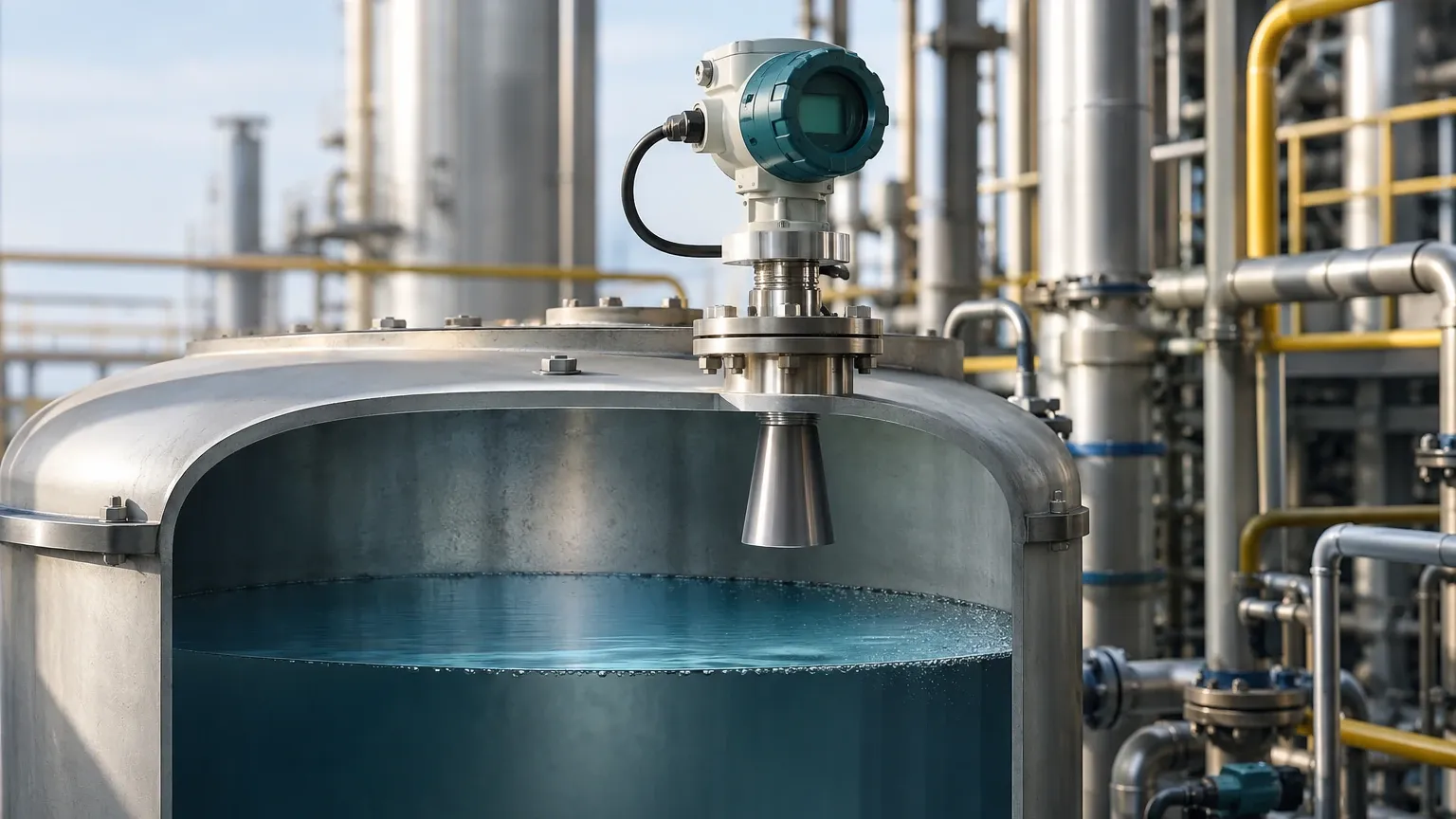
Even the most advanced radar level transmitter Yokogawa will fail to perform if installed incorrectly. Engineers must adhere to strict physical placement guidelines to ensure the microwave beam has a clear path to the product surface.
Nozzle Geometry
The mounting nozzle should be as short and wide as possible. If a nozzle is too long or narrow, the radar signal may reflect off the nozzle walls, creating a "near-zone" interference that prevents the instrument from measuring levels close to the top of the tank. For an 80 GHz transmitter, a 50 mm (2-inch) nozzle is often sufficient, whereas lower frequency units may require 100 mm (4-inch) or larger.
Beam Angle and Obstructions
The "beam angle" defines the spread of the microwave signal. It is measured at the point where the power density is half of its maximum value.
- Avoid the center: Do not mount the transmitter in the exact center of a domed-roof tank, as this can lead to multiple reflections that confuse the sensor.
- Distance from walls: Ensure the beam does not hit the tank wall. A general rule is to keep the mounting point at least 200 mm to 500 mm away from the wall, depending on the tank height and beam angle.
Stilling Wells and Bypass Pipes
In applications with heavy surface foam or extreme turbulence (e.g., near an agitator), installing the radar transmitter inside a stilling well or a bypass pipe (external chamber) can provide a calm surface for measurement. This also increases the signal strength for low-dielectric fluids by concentrating the microwave energy within the pipe.
5. Limitations and Application Risks
While radar technology is versatile, it is not a universal solution. Engineers must be aware of specific limitations:
1. Heavy Foam: While some radar frequencies can penetrate light foam, thick, dense foam (especially in chemical reactors) can absorb the radar signal entirely, leading to a "Loss of Echo" (LoE) error.
2. Vacuum Conditions: While radar works in a vacuum, the sealing materials (like PTFE or Kalrez) must be rated for vacuum service to prevent leakage into the instrument housing.
3. Condensation and Buildup: If the process medium is prone to heavy crystallization or condensation, the antenna may become coated. While many Yokogawa transmitters feature "Air Purge" connections to clean the antenna, extreme buildup will eventually attenuate the signal.
4. Solid Particles: In silos containing grain or minerals, the angle of repose (the slope of the material) can deflect the radar signal away from the receiver. High-frequency 80 GHz radars with specialized lenses are preferred here to capture reflections from slanted surfaces.
6. Maintenance and Calibration
Modern radar level transmitters are largely maintenance-free because they have no moving parts. However, periodic verification is required in regulated industries.
- Zero-Point Calibration: This involves verifying the distance from the sensor reference point to the bottom of the tank (the 0% level).
- Span Calibration: Verifying the 100% level, usually at the top of the tank.
- Echo Curve Analysis: Periodically reviewing the echo curve (the visual representation of the signal) allows technicians to identify if internal tank conditions have changed, such as the development of new obstructions or significant coating on the antenna.
7. Frequently Asked Questions (FAQ)
Q: Can a radar level transmitter Yokogawa be used for interface measurement?
A: Standard non-contact radar is generally not recommended for interface measurement (e.g., the boundary between oil and water). For these applications, Guided Wave Radar (GWR) is the preferred technology as the probe remains in contact with the media, allowing the signal to pass through the upper layer and reflect off the lower layer.
Q: How does temperature affect radar accuracy?
A: Unlike ultrasonic sensors, which are heavily affected by air temperature and density, radar signals travel at the speed of light and are virtually unaffected by temperature changes in the vapor space. This makes radar much more accurate in high-temperature steam applications.
Q: What is the difference between 2-wire and 4-wire transmitters?
A: 2-wire (loop-powered) transmitters use the same pair of wires for power and the 4-20mA signal, which simplifies wiring but limits available power. 4-wire transmitters have separate power supplies, allowing for more intensive signal processing and brighter displays, which can be useful in complex FMCW applications.
Q: Is it necessary to empty the tank for commissioning?
A: No. One of the primary advantages of non-contact radar is that it can be commissioned while the tank is in service. As long as the tank dimensions are known, the instrument can be configured via HART, FOUNDATION Fieldbus, or PROFIBUS.
Conclusion
The implementation of a radar level transmitter Yokogawa offers a high-reliability solution for complex industrial level challenges. By understanding the nuances of FMCW vs. Pulse technology, accounting for dielectric constants, and following precise installation geometries, engineering teams can ensure long-term operational success. For a broader range of industrial instrumentation and to compare different radar technologies, engineers should consult specialized resources on Radar Level Meters to find the optimal fit for their specific environmental and process constraints.