Radar Type Level Transmitter Working Principle
Radar Type Level Transmitter Working Principle: A Technical Guide for Industrial Applications
In the landscape of industrial process automation, accurate level measurement is critical for inventory management, process safety, and operational efficiency. Among the various technologies available, Radar Level Meters have emerged as a primary choice for challenging environments. Understanding the radar type level transmitter working principle is essential for engineers and procurement specialists to ensure the selected instrument matches the specific dielectric properties, vessel geometry, and atmospheric conditions of their application.
Radar technology offers a non-contact or guided-contact method of measuring the distance to a liquid or solid surface. Unlike ultrasonic sensors, which rely on sound waves and are susceptible to air temperature and pressure changes, radar utilizes electromagnetic waves that travel at the speed of light, providing high reliability in vacuum, high-pressure, and high-temperature scenarios.
The Core Radar Type Level Transmitter Working Principle
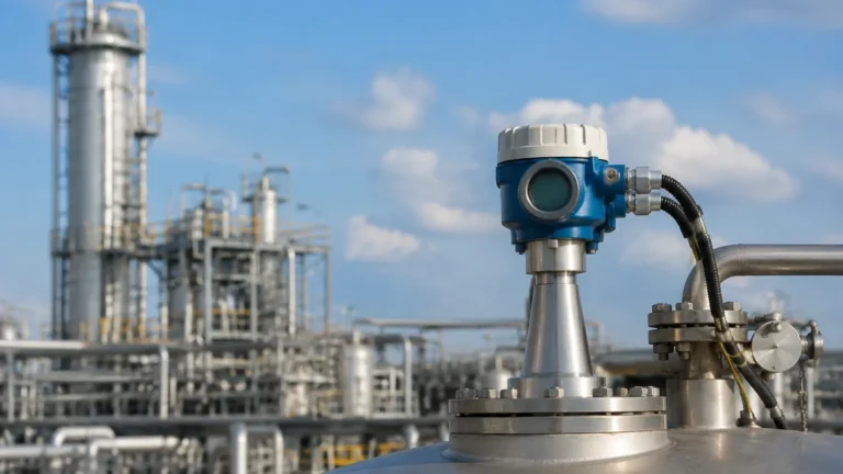
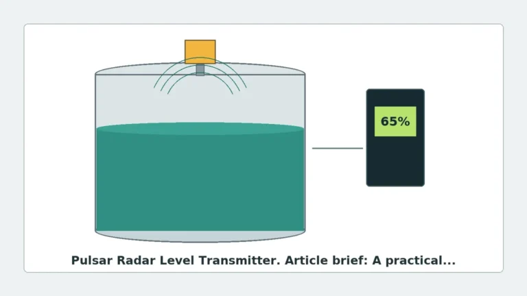
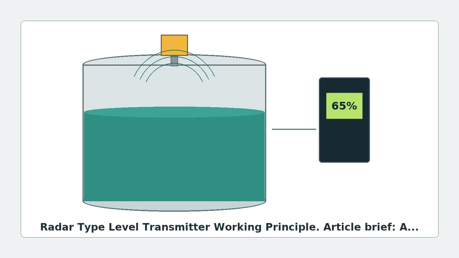
At its most fundamental level, a radar level transmitter operates by emitting high-frequency electromagnetic waves (microwaves) toward a target medium. These waves travel through the headspace of a vessel, reflect off the surface of the material, and return to the sensor's antenna. The transmitter then calculates the distance based on the properties of the returned signal.
There are two primary methods used to determine this distance: Pulse Radar and Frequency Modulated Continuous Wave (FMCW).
1. Pulse Radar (Time of Flight)
Pulse radar transmitters emit short bursts of microwave energy. After each pulse, the instrument switches to a receiving mode to listen for the echo. The distance ($D$) is calculated using the "Time of Flight" (ToF) principle:
$$D = \frac{c \times t}{2}$$
Where:
* $c$ is the speed of light (approximately 300,000 km/s).
* $t$ is the measured time delay between transmission and reception.
The division by two accounts for the round-trip travel of the signal. Pulse radar is generally energy-efficient and suitable for many standard industrial liquid level applications.
2. Frequency Modulated Continuous Wave (FMCW)
FMCW radar does not send discrete pulses; instead, it emits a continuous signal with a frequency that changes (sweeps) linearly over time. When the reflected signal is received, it is compared with the signal currently being emitted. Because the frequency of the emitted signal has changed during the time the wave took to travel to the surface and back, there is a frequency difference ($Δf$).
This frequency difference is directly proportional to the distance. FMCW radar typically offers higher accuracy and a better signal-to-noise ratio than pulse radar, making it the preferred choice for materials with low dielectric constants or in vessels with significant turbulence.
Guided Wave Radar vs. Non-Contact Radar
While the underlying radar type level transmitter working principle remains the same (electromagnetic wave reflection), the method of signal propagation differs between these two categories.
* Non-Contact Radar: The antenna radiates the signal through the air. This is ideal for corrosive or hygienic applications where the sensor should not touch the medium. However, the signal can be dispersed or obstructed by internal tank structures.
* Guided Wave Radar (GWR): The microwave signal is guided along a physical probe (rod or cable). This focuses the energy, minimizing signal loss and making it highly effective for low-dielectric liquids (like oils) or applications with heavy foam and steam that might scatter a non-contact signal.
Technical Factors Influencing Measurement
The Dielectric Constant ($ε_r$)
The dielectric constant of the medium is the most critical factor in radar measurement. It determines how much energy is reflected back to the sensor.
* High $ε_r$ (e.g., Water > 80): Excellent reflection, very easy to measure.
* Low $ε_r$ (e.g., Hydrocarbons 1.4 to 2.5): Most energy passes through the medium or is absorbed, leaving a weak reflection. In these cases, FMCW or Guided Wave Radar is often required.
Frequency Bands
Radar level meters operate at various frequencies, which dictate their performance characteristics:
* 6 GHz (C-Band): Longer wavelengths that can penetrate foam and dust but require larger antennas and have a wider beam angle.
* 26 GHz (K-Band): The industrial standard. It offers a balance of small antenna size and good accuracy for most liquids and solids.
* 80 GHz (W-Band): The latest advancement. It features an extremely narrow beam angle (as low as 3°), allowing it to avoid internal obstructions like agitators or heating coils. It is highly accurate and can measure through plastic tank walls.
Selection Criteria for Industrial Radar Level Meters
Choosing the right transmitter requires a comparison of process conditions against instrument capabilities. The following table provides a general selection framework:
| Feature | Pulse Radar (Non-Contact) | FMCW Radar (Non-Contact) | Guided Wave Radar (GWR) |
| :— | :— | :— | :— |
| Accuracy | ±3 mm to ±10 mm | ±1 mm to ±2 mm | ±2 mm to ±5 mm |
| Dielectric Constant | ε_r > 2.0 | ε_r > 1.4 | ε_r > 1.4 |
| Max Range | Up to 30 meters | Up to 120 meters | Up to 75 meters |
| Turbulence/Foam | Moderate resistance | High resistance | Best resistance |
| Internal Obstacles| Sensitive to beam path | Better (80GHz) | Not affected (if probe is clear) |
| Typical Application| Water tanks, simple chemicals | High-precision storage, solids | Oil/Water interface, low ε_r liquids |
Installation Guidelines and Constraints
To ensure the radar type level transmitter working principle functions effectively in a real-world environment, specific installation rules must be followed:
1. Beam Path Clearance: The "beam angle" of the radar must be kept clear of obstructions such as ladders, pipes, or agitators. If the signal hits these objects, it creates "false echoes."
2. Nozzle Height and Diameter: The antenna should ideally extend slightly beyond the mounting nozzle to prevent signal interference from the nozzle walls. If the nozzle is long, a waveguide or a specific nozzle-extension antenna should be used.
3. Avoid the Center: Do not mount the radar in the exact center of a domed tank, as this can concentrate multiple reflections (parabolic effect) and confuse the sensor.
4. Perpendicular Alignment: The transmitter must be mounted perpendicular to the product surface to ensure the maximum amount of reflected energy returns to the antenna.
5. Inlet Proximity: Never install the sensor directly above the filling inlet. The falling stream will cause signal noise and erratic readings.
Limitations and Application Risks
Despite their versatility, radar level meters are not universal solutions. Engineers must account for the following risks:
* Heavy Foam: While some radar frequencies can penetrate light foam, extremely thick, dense foam (like that found in some chemical reactors) can absorb the microwave signal entirely, resulting in a "loss of echo."
* Condensation and Buildup: If the medium is prone to heavy crystallization or coating, the antenna can become covered. While many modern Radar Level Meters feature "false echo suppression" software, physical buildup can eventually attenuate the signal.
* Vacuum and Pressure: While radar works in a vacuum, the mechanical seals and flange ratings of the instrument must be verified for high-pressure applications (e.g., >40 bar).
* Dielectric Shifting: If the composition of the liquid changes significantly (changing its ε_r), the strength of the reflection will change. While this doesn't usually affect the distance calculation for non-contact radar, it can affect GWR signal tracking.
Maintenance and Troubleshooting
Radar level transmitters are generally low-maintenance because they have no moving parts. However, troubleshooting is occasionally necessary:
* Signal Loss: Often caused by antenna coating or the dielectric constant being lower than the instrument's minimum threshold. Cleaning the antenna or switching to a GWR probe may be necessary.
* Erratic Readings: Usually the result of interference from agitators. This can often be solved by using the "map out" or "background subtraction" feature in the transmitter's software, which tells the unit to ignore static reflections at specific distances.
* Inaccurate Level: Check if the "Upper Blocking Distance" (dead zone) is set correctly. Radar units have a small area near the antenna where measurement is not possible.
Frequently Asked Questions (FAQ)
Q: Can radar measure the interface between two liquids?
A: Yes, Guided Wave Radar is specifically designed for this. It can detect the top of an upper layer (e.g., oil) and the interface of a lower layer (e.g., water), provided the upper layer has a lower dielectric constant and is non-conductive.
Q: Is 80 GHz always better than 26 GHz?
A: Not necessarily. While 80 GHz offers better focus and accuracy, 26 GHz or 6 GHz may be better for applications with heavy steam or dust, as longer wavelengths are less affected by airborne particles.
Q: Does the tank material affect the radar?
A: If the tank is metal, it acts as a Faraday cage, containing the signal. If the tank is plastic or fiberglass, the radar signal may pass through the tank wall. This allows for non-intrusive measurement from outside the tank, but it also means the radar might pick up reflections from objects outside the tank.
Q: What is the "Dead Zone"?
A: The dead zone (or blocking distance) is the area immediately below the antenna where the transmitter cannot accurately process the return signal. This typically ranges from 50 mm to 300 mm depending on the frequency and antenna type.
Conclusion
Understanding the radar type level transmitter working principle allows for the precise selection of instrumentation that can withstand the rigors of industrial processing. By evaluating the dielectric constant of the medium, the vessel's internal geometry, and the required accuracy, facilities can implement level measurement solutions that reduce downtime and improve safety. For high-performance environments, leveraging advanced 80 GHz technology or Guided Wave Radar ensures that even the most difficult materials are monitored with surgical precision.
Download Radar Type Level Transmitter Working Principle as a PDF