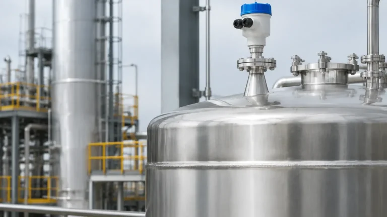
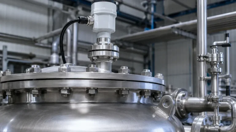
Pulsar Radar Level Transmitter
Pulsar Radar Level Transmitter: A Technical Guide to Pulse-Based Level Measurement
In the landscape of industrial process control, the pulsar radar level transmitter represents a cornerstone technology for non-contact level measurement. By utilizing microwave pulses to determine the distance to a material surface, these instruments provide reliable data in environments where traditional contact sensors—such as floats or displacers—would fail due to corrosion, viscosity, or mechanical wear.
For engineers and procurement professionals, understanding the nuances of pulse-based radar technology is essential for ensuring process safety and efficiency. This guide examines the operating principles, selection criteria, and installation requirements for Radar Level Meters used across the water treatment, chemical, and oil and gas sectors.
1. Measurement Principles of Pulsar Radar Technology
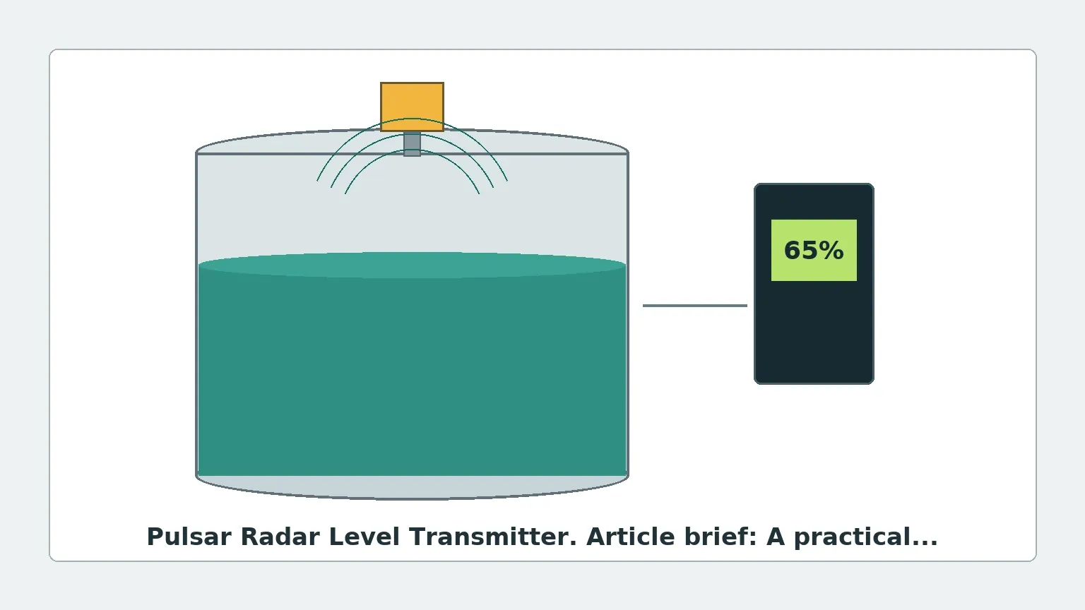
The pulsar radar level transmitter operates on the "Time of Flight" (ToF) principle, specifically using pulsed microwave signals. Unlike Frequency Modulated Continuous Wave (FMCW) radar, which emits a continuous signal, a pulsed radar device sends out discrete bursts of electromagnetic energy.
The Pulse-Echo Cycle
1. Emission: The transmitter's antenna emits a high-frequency microwave pulse (typically in the 6 GHz to 80 GHz range) toward the target medium.
2. Reflection: When the pulse hits the surface of the medium, a portion of the energy is reflected back toward the sensor. The strength of this reflection depends heavily on the Dielectric Constant (εr) of the material.
3. Reception: The antenna receives the reflected signal (the echo).
4. Calculation: The integrated electronics measure the time interval between the emission and the reception. Since the speed of light is constant, the distance is calculated using the formula:
*Distance = (Speed of Light × Travel Time) / 2.*
Signal Processing and Echo Filtering
Modern pulsar radar level transmitters employ advanced signal processing algorithms to distinguish the "true echo" from false reflections caused by tank internals like agitators, ladders, or heating coils. This process, often referred to as "echo mapping" or "false signal suppression," allows the transmitter to maintain accuracy even in complex vessel geometries.
2. Selection Criteria for Industrial Applications
Choosing the correct radar level transmitter requires a detailed analysis of the process environment. The following table provides a comparison of key factors influencing the selection of pulse-based radar systems.
Technical Selection Matrix
| Feature | Specification / Requirement | Engineering Consideration |
| :— | :— | :— |
| Frequency | 6 GHz (C-Band) to 80 GHz (W-Band) | Lower frequencies handle steam/foam better; higher frequencies offer narrower beam angles. |
| Measuring Range | 0.3 m to 70 m (1 ft to 230 ft) | Ensure the transmitter's "dead zone" (near-field) does not interfere with maximum fill levels. |
| Dielectric Constant | εr ≥ 1.4 | Materials with low εr (e.g., oils) reflect less energy and may require guided wave radar or high-sensitivity pulsar units. |
| Process Pressure | Vacuum to 40 bar (580 psi) | High-pressure applications require specialized flange seals and robust antenna housing. |
| Process Temperature | -40°C to +250°C (-40°F to 482°F) | Extreme temperatures necessitate cooling fins or remote electronics. |
| Output Signal | 4-20mA HART, RS485 Modbus, Profibus | Compatibility with existing PLC/DCS architectures is vital for automation. |
3. Installation Considerations and Best Practices
The accuracy of a pulsar radar level transmitter is highly dependent on its physical placement. Incorrect installation is the leading cause of signal loss and measurement drift.
Beam Angle and Obstructions
The radar signal spreads in a cone shape. The beam angle is determined by the antenna frequency and size.
* Clearance: The signal cone must not intersect with the tank wall or internal structures. If the beam hits a ladder, it will report a false static level.
* Nozzle Mounting: The antenna should ideally extend slightly beyond the mounting nozzle to prevent "ringing" or internal reflections within the nozzle neck. For nozzles longer than 150 mm (6 in), a horn antenna extension may be required.
Positioning on the Vessel
* Avoid the Center: In cylindrical tanks with domed tops, do not mount the transmitter in the exact center. This can lead to multiple reflections (parabolic effect) that confuse the sensor.
* Distance from Wall: Maintain a minimum distance from the tank wall, typically 1/6th of the tank diameter, to avoid interference from side-wall build-up or weld seams.
* Inlet Streams: Never install the sensor directly above the filling inlet. The turbulence and falling material will cause significant signal noise.
4. Limitations and Application Risks
While highly versatile, pulsar radar level transmitters are not universal solutions. Engineers must account for the following limitations:
1. Heavy Foam: Dense, thick foam can absorb microwave signals entirely, leading to a "Loss of Echo" (LoE) error. In such cases, a low-frequency radar (6 GHz) or a different technology like a magnetic level gauge may be more appropriate.
2. Low Dielectric Media: Liquid hydrocarbons (like hexane or toluene) have very low dielectric constants. If the εr is below 1.9, the reflection may be too weak for a standard pulsar radar to detect reliably without a stilling well.
3. Dust and Condensation: While radar penetrates dust better than ultrasonic sensors, heavy build-up on the antenna lens can attenuate the signal. Transmitters with PTFE-faced antennas or air-purge connections are recommended for these environments.
4. Agitation: Rapidly swirling surfaces or heavy vortices can scatter the radar signal. Signal damping settings in the transmitter software can help, but a stilling well is often the most robust mechanical solution.
5. Application Profiles
Water and Wastewater Treatment
In open channels or wet wells, pulsar radar transmitters are used for flow measurement and level monitoring. Because they are non-contact, they are unaffected by the debris and corrosive gases (like H2S) common in sewage treatment.
Chemical Processing
For acids and alkalis, transmitters are often equipped with PTFE or PVDF wetted parts. The pulsar radar's ability to measure through plastic tank walls (if the material is non-conductive) allows for "through-wall" measurement, keeping the sensor entirely isolated from the hazardous medium.
Oil and Gas Storage
In large storage tanks, high-precision radar is used for inventory control. The pulsar radar level transmitter provides the necessary range (up to 70m) and can be integrated into tank gauging systems for Custody Transfer applications.
6. International Buyer’s Checklist
When sourcing industrial level measurement equipment from global manufacturers like Welk, international buyers should confirm the following technical details to ensure compliance and compatibility:
* Certifications: Does the application require ATEX, IECEx, or SIL2/3 functional safety ratings?
* Wetted Materials: Confirm that the antenna material (e.g., 316L Stainless Steel, Hastelloy, or PTFE) is chemically compatible with the process fluid.
* Thread/Flange Standards: Specify whether ANSI, DIN, or JIS flanges are required to match existing vessel connections.
* Power Supply: Ensure the device supports the local industrial voltage (typically 24V DC for 2-wire loop-powered units).
* Environmental Protection: For outdoor installations in tropical or arctic climates, verify the IP rating (IP66/67/68) and operating temperature range of the housing.
7. Frequently Asked Questions (FAQ)
Q: How does a pulsar radar level transmitter differ from an ultrasonic level sensor?
A: Radar uses electromagnetic waves, which travel at the speed of light and are unaffected by air temperature, pressure, or vacuum. Ultrasonic sensors use sound waves, which require a medium (air) to travel and are highly sensitive to temperature fluctuations and vapor layers.
Q: Can pulsar radar measure solids and powders?
A: Yes, but it requires a higher frequency (typically 26 GHz or 80 GHz) and often a swiveling flange to aim the beam at the material's angle of repose. Dust-intensive applications also benefit from air-purging systems.
Q: What is the "Dead Zone" in radar measurement?
A: The dead zone (or blocking distance) is the area immediately below the antenna where the transmitter cannot accurately measure because the pulse emission and reception happen too quickly for the electronics to resolve. This is typically between 50 mm and 300 mm (2 in to 12 in).
Q: Is maintenance required for these transmitters?
A: Because they have no moving parts, maintenance is minimal. Periodic inspection of the antenna for build-up and verifying the accuracy against a manual dip-tape measurement is usually sufficient for annual maintenance cycles.
For more detailed specifications on high-frequency and pulse-based systems, professionals can Review product options and application support to find the optimal configuration for their specific industrial requirements.