Rosemount Radar Level Transmitter 5402
Rosemount Radar Level Transmitter 5402: Technical Engineering Guide
In the field of industrial process automation, precise level measurement is a cornerstone of operational safety and efficiency. Among the various technologies available, non-contacting radar has emerged as a preferred solution for challenging environments. The Rosemount radar level transmitter 5402, part of the widely utilized 5400 series, represents a specific engineering approach to microwave-based measurement. This guide provides a comprehensive technical analysis of the 5402's operating principles, selection criteria, and installation requirements for engineers and procurement specialists.
Understanding Non-Contacting Radar Principles
Before evaluating specific hardware like the Rosemount 5402, it is essential to understand the physics of radar-based level detection. Most modern Radar Level Meters operate on the Time of Flight (ToF) principle.
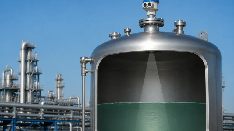
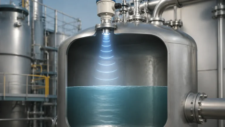
Non-contacting radar transmitters emit micro-pulses of electromagnetic energy (microwaves) toward the surface of the process medium. When these pulses hit the product surface, a portion of the energy is reflected back to the transmitter's antenna. Because microwaves travel at the speed of light, the transmitter can calculate the distance to the product surface by measuring the time interval between the emission of the pulse and the reception of the echo.
Distance is calculated using the formula:
$$D = \frac{c \times t}{2}$$
Where:
* D is the distance to the surface.
* c is the speed of light.
* t is the measured time delay.
The Rosemount radar level transmitter 5402 specifically utilizes a high-frequency (approximately 26 GHz) signal. Higher frequencies allow for shorter wavelengths, which results in smaller antenna sizes and narrower beam widths. This is particularly advantageous in industrial tanks where internal obstructions like agitators, ladders, or heating coils might otherwise interfere with the signal.
Technical Specifications and Performance Capabilities
The 5402 is designed as a 2-wire transmitter, typically powered by a 24V DC loop, making it compatible with standard industrial control systems. It is engineered to handle liquids, slurries, and some solid materials across a range of industries, from chemical processing to water treatment.
Key Technical Parameters
| Feature | Specification (Metric) | Specification (Imperial) |
| :— | :— | :— |
| Measurement Range | Up to 35 meters | Up to 115 feet |
| Accuracy | ± 3 mm | ± 0.12 inches |
| Operating Frequency | ~26 GHz (K-band) | ~26 GHz (K-band) |
| Process Temperature | -40°C to +250°C | -40°F to +482°F |
| Process Pressure | Vacuum to 50 bar | Vacuum to 725 psi |
| Output Signal | 4-20 mA / HART, Foundation Fieldbus | 4-20 mA / HART, Foundation Fieldbus |
One of the defining features of the 5402 is its "Dual Port Technology." This engineering design allows the transmitter to handle higher signal-to-noise ratios by utilizing separate paths for transmitting and receiving signals within the same circular housing. This increases the sensitivity of the device, allowing it to detect surfaces with low dielectric constants or in conditions where the signal might be weakened by turbulence.
Selection Criteria for Industrial Applications
Choosing the correct configuration for a Rosemount radar level transmitter 5402 requires an analysis of the process medium and the vessel geometry. The following factors are critical during the specification phase:
1. Dielectric Constant ($ε_r$)
Radar signals reflect off the surface based on the dielectric constant of the material. Materials with high dielectric constants (e.g., water, $ε_r ≈ 80$) produce strong reflections. Materials with low dielectric constants (e.g., hydrocarbons, $ε_r < 2.0$) reflect less energy. The 5402 is capable of measuring low-dielectric products, but the antenna type and signal processing settings must be adjusted accordingly.
2. Antenna Type
The 5402 offers several antenna options:
* Cone Antenna: The most common choice for large tanks. It is robust and available in various sizes (50mm to 100mm). Larger cones provide narrower beams.
* Process Seal Antenna: Used for corrosive or hygienic applications where the transmitter must be isolated from the process environment.
* Parabolic Antenna: Ideal for very long ranges or materials with extremely low reflectivity.
3. Vapor and Condensation
While radar is generally unaffected by pressure and temperature changes in the vapor space, heavy steam or condensation on the antenna can attenuate the signal. In such cases, choosing an antenna with a PTFE shield or a flushing connection is recommended.
Installation Constraints and Best Practices
The reliability of Radar Level Meters is heavily dependent on correct physical installation. Even a high-performance unit like the Rosemount radar level transmitter 5402 will fail if positioned incorrectly.
Positioning and Clearance
* Wall Distance: The transmitter should be installed at least 300 mm (12 inches) away from the tank wall to avoid "ringing" or false reflections from the wall surface.
* Inlet Interference: Never install the transmitter directly above the product inlet. The turbulence and falling material will create significant signal noise.
* Vertical Alignment: The antenna must be mounted perpendicular to the product surface. An inclination of even a few degrees can cause the reflected signal to miss the receiver, especially in low-dielectric applications.
Nozzle Requirements
The nozzle height and diameter play a vital role. If the nozzle is too narrow or too long, the radar beam will reflect off the nozzle's internal edges before reaching the tank.
* Nozzle Diameter: Should ideally match the antenna diameter.
* Nozzle Height: The antenna should extend at least 10 mm (0.4 inches) below the bottom of the nozzle to ensure the beam clears the mounting flange without interference.
Obstruction Management
Internal structures like agitator blades, baffles, and ladders are common in industrial vessels. The Rosemount 5402 utilizes "Echo Log" and "False Echo Suppression" software. During commissioning, the engineer should perform a "tank map" while the vessel is empty. This allows the transmitter to identify and ignore static reflections from internal hardware.

Signal Processing and Troubleshooting
The 5402 utilizes advanced algorithms to differentiate between the true product level and parasitic noise. However, certain conditions can still challenge the system.
Signal Loss (High Noise)
If the transmitter reports a "Signal Lost" error, it often indicates that the reflected energy is too weak. This can be caused by:
* Heavy Foam: Some foams absorb microwave energy rather than reflecting it. If foam is thick and dense, a guided wave radar or a different frequency might be required.
* Extreme Turbulence: A boiling or heavily agitated surface scatters the radar beam. Increasing the damping value in the software can help smooth out the readings.
False High Levels
If the transmitter consistently reads a level higher than the actual product, check for condensation or buildup on the antenna lens. A simple cleaning or the addition of a weather shield can often resolve these issues.
Limitations and Application Risks
While the Rosemount radar level transmitter 5402 is a versatile tool, it is not a universal solution. Engineers must be aware of the following limitations:
1. Vacuum Conditions: While radar works in a vacuum, the mechanical seals and flanges must be rated for vacuum service to prevent air ingress or transmitter damage.
2. Solid Materials: While the 5402 can measure solids, the angle of repose (the slope of the pile) can deflect the signal away from the antenna. For heavy dust or steep angles, specialized solids radar units are often more effective.
3. Extremely Low Dielectrics: For liquefied gases or pure refrigerants with $ε_r < 1.4$, the reflection may be too weak for standard non-contacting radar. In these scenarios, a Guided Wave Radar (GWR) is typically preferred as the probe concentrates the energy.
Frequently Asked Questions (FAQ)
Q: Can the Rosemount 5402 be used for interface measurement?
A: Generally, no. Non-contacting radar is designed to detect the top surface of the uppermost liquid. For measuring the interface between two liquids (e.g., oil and water), Guided Wave Radar is the industry standard.
Q: Does the 5402 require periodic recalibration?
A: Because radar is a time-of-flight technology based on the speed of light, it does not suffer from the "drift" associated with pressure-based or mechanical level sensors. However, annual verification is recommended to ensure the antenna is clean and the electronics are functioning within spec.
Q: What is the impact of heavy dust on the 5402?
A: The 26 GHz frequency used by the 5402 is relatively resistant to dust. However, if the dust is metallic or extremely dense, it may attenuate the signal. Regular inspection of the antenna face is advised in dusty environments.
Q: How does the 5402 handle internal tank agitators?
A: The transmitter includes a software feature called "Variable Guard Track." This allows the device to track the level even when an agitator blade passes through the beam path, by ignoring the intermittent high-amplitude spikes caused by the blades.
Conclusion
The Rosemount radar level transmitter 5402 is a robust instrument for non-contacting level measurement, offering high precision and reliability through its 26 GHz frequency and dual-port design. Success with this device depends on a thorough understanding of the process dielectric properties and strict adherence to installation geometry. By following the guidelines for nozzle placement and signal mapping, engineers can ensure long-term, maintenance-free operation in a wide variety of industrial liquid applications.