Uwt Radar Level Transmitter
UWT Radar Level Transmitter: A Technical Guide to Non-Contact Measurement
In the landscape of industrial process automation, the transition from mechanical level measurement to electronic, non-contact sensing has significantly improved operational reliability. Among the most robust technologies available today is the radar level transmitter. This guide examines the engineering principles, selection criteria, and installation requirements for the uwt radar level transmitter and similar high-frequency Radar Level Meters, providing a technical foundation for engineers and procurement specialists.
1. Principles of Radar Level Measurement
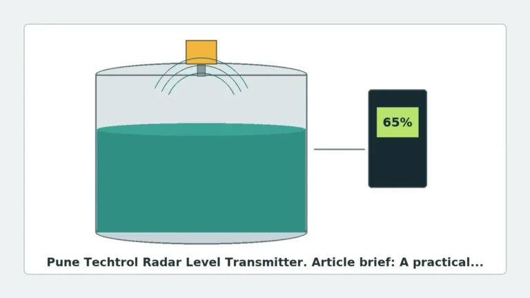
Radar level measurement is based on the propagation of electromagnetic waves. Unlike ultrasonic sensors, which rely on sound waves and are susceptible to air temperature and pressure changes, radar waves travel at the speed of light and are largely unaffected by the atmosphere within a vessel.
Time of Flight (ToF) vs. FMCW
There are two primary methods used in radar level transmitters:
1. Pulse Radar (Time of Flight): The device emits a short microwave pulse that reflects off the surface of the medium. The sensor measures the time elapsed between emission and reception. While effective, pulse radar often requires higher dielectric constants to achieve high precision.
2. Frequency Modulated Continuous Wave (FMCW): This is the technology typically found in high-end units like the uwt radar level transmitter series. The transmitter emits a continuous signal with a constantly changing frequency. The difference in frequency between the emitted and received signal is proportional to the distance. FMCW offers superior accuracy and a better signal-to-noise ratio, making it ideal for complex environments with dust or turbulence.
The Role of Frequency
The frequency of the radar signal (measured in GHz) determines the beam angle and the ability of the sensor to handle obstacles.
- 26 GHz Radar: Standard for many liquid applications; offers a balance between signal strength and beam width.
- 80 GHz Radar: The current state-of-the-art. It provides a very narrow beam angle (often as low as 3°), allowing the signal to bypass internal tank obstructions like agitators or ladders. This high frequency is particularly effective for measuring solids with a low angle of repose.
2. Technical Selection Criteria
Choosing the correct uwt radar level transmitter requires a deep understanding of the process media and the vessel environment. The following factors are critical for a successful specification.
Dielectric Constant (εr)
The dielectric constant of the material is the most important factor in radar measurement. It determines how much energy is reflected back to the sensor.
- High εr (>10): Materials like water or acids reflect signals strongly.
- Low εr (1.4 – 4): Materials like plastic pellets, oils, or dry powders reflect very little energy. In these cases, a high-sensitivity FMCW transmitter or a guided wave radar may be necessary.
Process Conditions
Engineers must confirm the maximum operating pressure and temperature. Standard radar sensors often handle up to 40 bar and 200°C, but specialized high-temperature versions are required for molten materials or high-pressure steam applications.
Material State: Solids vs. Liquids
Measuring solids introduces challenges such as dust, uneven surfaces, and the "angle of repose." A uwt radar level transmitter designed for solids (such as the NivoRadar series) typically features a lens antenna or a specialized aiming flange to account for the slanted surface of the material pile.
3. Comparison Table: Radar Technology Specifications
| Feature | 26 GHz Radar | 80 GHz Radar | Guided Wave Radar (GWR) |
| :— | :— | :— | :— |
| Measurement Range | Up to 30m | Up to 100m | Up to 75m |
| Accuracy | ±3 mm | ±1 mm | ±2 mm |
| Beam Angle | 8° – 20° | 3° – 8° | N/A (Guided by probe) |
| Dust Resistance | Moderate | Excellent | Excellent |
| Foam Resistance | Poor | Moderate | Good |
| Best Use Case | Large liquid tanks | Tall silos, solids | Small vessels, low εr |
4. Installation and Engineering Considerations
Even the most advanced uwt radar level transmitter will fail if installed incorrectly. Engineering teams should adhere to the following checklist during the design phase.
Blocking Distance (Dead Zone)
Every radar sensor has a minimum distance (dead zone) near the antenna where measurement is not possible. Ensure that the maximum fill level of the tank does not enter this zone, which is typically between 50mm and 200mm depending on the model.
Nozzle Geometry
The mounting nozzle should be as short as possible. If the nozzle is too long or narrow, it can cause internal reflections (ringing) that interfere with the initial signal. For 80 GHz sensors, nozzle interference is minimized due to the narrow beam, but it remains a consideration for 26 GHz units.
Avoiding Obstructions
The "signal cone" must be clear of internal structures.
- Agitators: If an agitator is present, the radar should be mounted off-center. Some transmitters offer "false signal suppression" software to map out and ignore static reflections from blades.
- Inflow: Never mount the sensor directly above the material inlet, as the falling stream will cause erratic readings.
Orientation for Solids
When measuring bulk solids, the sensor should ideally be mounted 1/3 of the way from the tank wall to the center. For silos with significant peaking or cratering, an adjustable flange allows the engineer to aim the radar beam at the most representative point of the material surface.
5. Limitations and Application Risks
While radar is highly versatile, it is not a universal solution. Engineers must be aware of specific limitations:
* Heavy Foam: Thick, dense foam can absorb the radar signal entirely, leading to a "loss of echo" error. In such cases, a displacement transmitter or a magnetic level gauge may be more appropriate.
* Extremely Low Dielectric Media: If the εr is below 1.4, the radar signal may pass through the material and reflect off the bottom of the tank.
* Condensation: While many uwt radar level transmitter models feature PTFE-coated lens antennas to shed moisture, heavy condensation or material buildup can still attenuate the signal. Integrated air purging systems are recommended for extremely dusty or humid silos.
6. Maintenance and Calibration
Modern digital radar meters are virtually maintenance-free because they have no moving parts. However, periodic verification is recommended for safety-critical applications (SIL-rated loops).
1. Signal Quality Monitoring: Most smart transmitters provide a "Signal-to-Noise Ratio" (SNR). A declining SNR over time usually indicates material buildup on the antenna or a failing seal.
2. Remote Configuration: Utilizing HART, Profibus, or Modbus protocols allows technicians to adjust the "echo curve" remotely without climbing to the top of the vessel.
3. Visual Inspection: In abrasive solid applications, check the antenna lens for physical wear or pitting caused by high-velocity dust particles.
7. Frequently Asked Questions (FAQs)
Q: Can a radar level transmitter measure through a plastic tank lid?
A: Yes. Because plastic is non-conductive and has a low dielectric constant, radar waves can penetrate plastic or fiberglass covers. This allows for "tank-side" measurement without cutting a hole in the vessel, provided the lid is not metallic.
Q: How does dust affect the uwt radar level transmitter?
A: High-frequency radar (80 GHz) is largely unaffected by dust because the wavelength is significantly larger than the dust particles. However, in extreme cases, an air purge connection is used to keep the lens clean.
Q: What is the difference between 2-wire and 4-wire radar?
A: 2-wire (loop-powered) transmitters are easier to install as they use the same pair of wires for power and the 4-20mA signal. 4-wire transmitters have separate power supplies and are typically used when high power is needed for heating elements or complex signal processing.
Conclusion
The selection of a uwt radar level transmitter represents a significant investment in process accuracy and safety. By understanding the nuances of FMCW technology, frequency selection, and the physical constraints of the vessel, engineers can ensure long-term reliability. For diverse industrial needs, exploring the full range of Radar Level Meters is the first step toward optimizing inventory management and process control. When specifying equipment, always provide the manufacturer with the material's dielectric constant and a detailed tank drawing to ensure the chosen solution matches the application's demands.