Radar Level Transmitter 5408a
Radar Level Transmitter 5408a: Engineering Guide for Non-Contacting Measurement
In the landscape of industrial process automation, the demand for high-precision, low-maintenance level measurement has led to the widespread adoption of frequency-modulated continuous wave (FMCW) technology. The radar level transmitter 5408a represents a significant evolution in this field, designed to meet the rigorous safety and reliability requirements of modern chemical, oil and gas, and power generation facilities. This guide provides a technical overview of the operating principles, selection criteria, and installation requirements for the 5408a and similar high-performance Radar Level Meters.
1. Understanding the FMCW Measurement Principle
Unlike traditional pulse-based radar, which measures the time-of-flight of a single microwave burst, the radar level transmitter 5408a utilizes Frequency Modulated Continuous Wave (FMCW) technology. This principle is fundamental to its superior accuracy and signal-to-noise ratio.
The Sawtooth Signal
In FMCW measurement, the transmitter emits a continuous signal with a frequency that changes linearly over time, creating a "sweep" or "chirp." When this signal reaches the surface of the medium, it is reflected back to the antenna. Because the transmitter is constantly changing its frequency, by the time the reflected signal returns, the transmitter is already emitting a different frequency.
Beat Frequency Calculation
The electronics within the transmitter compare the frequency of the received signal with the frequency of the signal being transmitted at that exact moment. The difference between these two frequencies is known as the "beat frequency." This beat frequency is directly proportional to the distance between the antenna and the product surface. The relationship can be expressed as:
$$d = \frac{c \cdot \Delta f}{2 \cdot S}$$
Where:
* d is the distance to the product.
* c is the speed of light.
* Δf is the beat frequency.
* S is the rate of the frequency sweep (slope).
Because FMCW technology integrates the signal over a longer period compared to pulse radar, it can effectively filter out noise caused by turbulence, foam, or internal tank obstructions, providing a much more stable and reliable reading.
2. Key Features of the 5408a Series
The 5408a is engineered for "Safety by Design," often utilized in SIL 2 and SIL 3 applications. Its architecture focuses on reducing the likelihood of undetected failures, which is critical in hazardous environments.
Non-Contacting Design
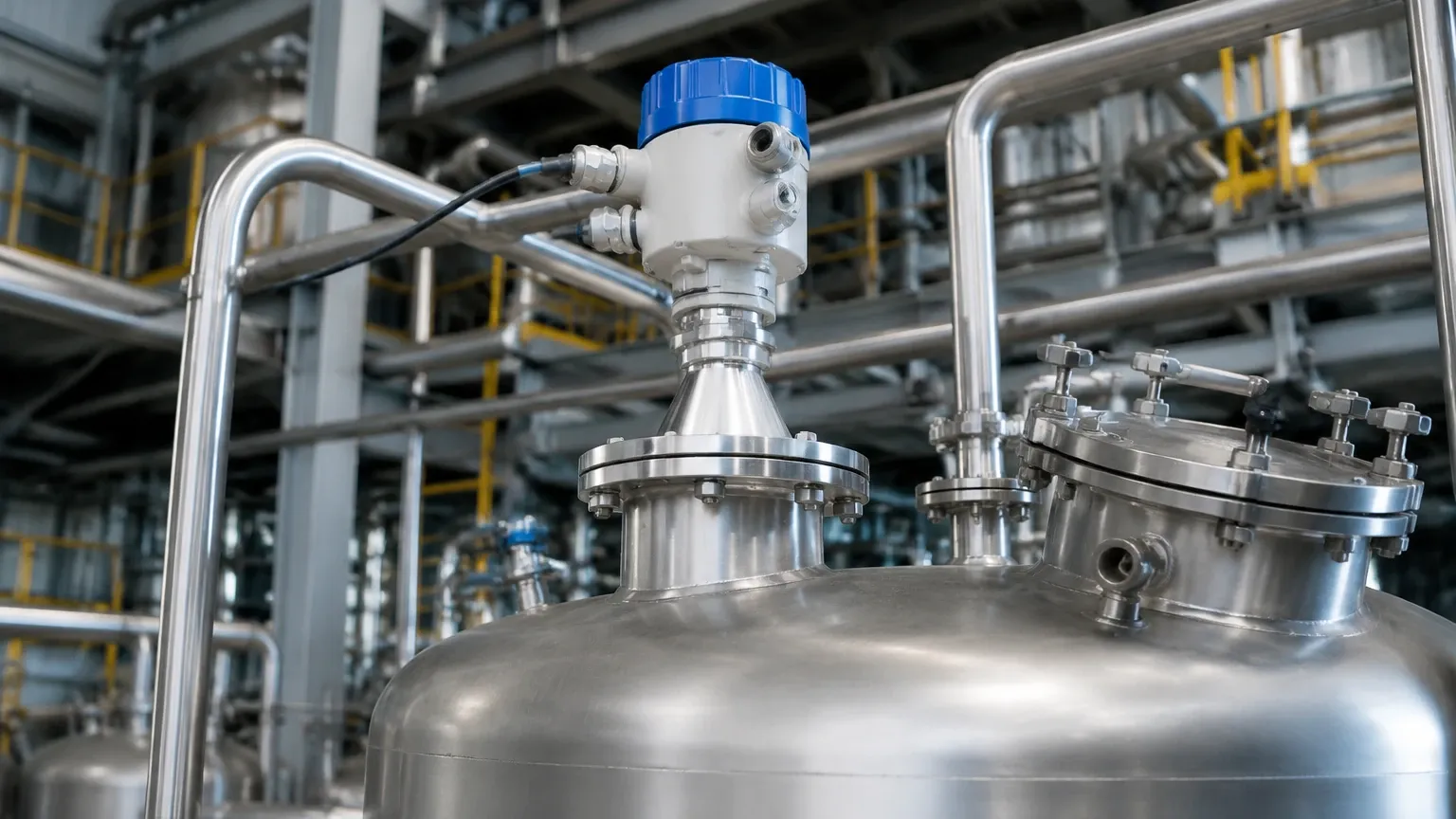
As a non-contacting instrument, the radar level transmitter 5408a does not come into physical contact with the process media. This eliminates concerns regarding corrosion, coating, or mechanical wear on the sensing element, significantly reducing long-term maintenance costs and increasing the lifespan of the device.
High Sensitivity and Dynamic Range
Modern FMCW transmitters feature a wide dynamic range, allowing them to detect weak reflections from materials with a low dielectric constant (DK), such as liquefied gases or certain hydrocarbons, even in the presence of heavy vapor or dust.
Dual-Compartment Housing
The hardware is typically designed with a dual-compartment housing. This separates the electronics from the terminal compartment, protecting the sensitive circuit boards from moisture and environmental contaminants during wiring and commissioning.
3. Technical Selection Criteria
Selecting the correct configuration for a radar level transmitter 5408a requires an analysis of the process conditions and the physical characteristics of the storage vessel. Use the following table as a baseline for engineering selection.
Selection Table: Process Compatibility
| Feature | Specification Range (Typical) | Engineering Consideration |
| :— | :— | :— |
| Measurement Range | Up to 40m (Standard) / 75m (Extended) | Ensure the nozzle height is accounted for in the total range. |
| Process Temperature | -60°C to +250°C | High-temperature extensions are required for steam or molten processes. |
| Process Pressure | Vacuum to 100 bar (1450 psi) | Check flange ratings (ANSI/EN) against maximum surge pressure. |
| Accuracy | ±1 mm to ±3 mm | Critical for custody transfer or high-value chemical dosing. |
| Beam Angle | 3° to 10° (depending on antenna) | Narrower beams are better for tall, narrow tanks with obstructions. |
| Dielectric Constant | > 1.2 | Lower DK materials require larger antennas or specialized signal processing. |
Antenna Types
* Cone/Horn Antenna: The most versatile option, suitable for most liquid and solid applications. Available in various sizes (2", 3", 4") to balance signal strength and nozzle size.
* Process Seal Antenna: Features a PTFE or PEEK face that protects the antenna from corrosive vapors and prevents condensation buildup.
* Parabolic Antenna: Used primarily for very long-range applications or materials with extremely low reflectivity (solids/powders).
4. Installation Considerations and Best Practices
The performance of Radar Level Meters is heavily dependent on proper physical installation. Even the most advanced FMCW transmitter will fail if the signal path is obstructed.
Nozzle Geometry
The nozzle should be as short as possible. If the nozzle is too long or narrow, the radar signal can reflect off the internal walls of the nozzle, creating "ringing" or a large dead zone at the top of the tank. Ideally, the antenna should extend slightly below the bottom of the nozzle.
Obstruction Avoidance
The radar beam spreads as it travels. Any internal structures within this "cone"—such as heating coils, agitator blades, ladders, or inlet pipes—will create false echoes.
* Rule of Thumb: Maintain a minimum distance of 200 mm (8 inches) from the tank wall to avoid side-wall interference.
* Agitators: If an agitator is present, the transmitter’s software must be configured with a "False Echo Map" to ignore the periodic reflections caused by the moving blades.
Mounting Position
Do not mount the transmitter in the center of a tank with a domed roof, as the curved surface can act as a parabolic reflector, concentrating noise and multiple-bounce reflections back at the sensor. The ideal position is usually 1/3 of the radius from the tank wall.
5. Limitations and Application Risks
While the radar level transmitter 5408a is highly robust, certain environmental factors can impact its performance.
1. Heavy Foam: While FMCW is better at penetrating foam than pulse radar, extremely dense, thick foam (like protein-based fire-fighting foam) can absorb the microwave signal entirely, leading to a loss of echo.
2. Rapid Pressure Changes: In high-pressure gas phases (e.g., CO2 or Ammonia), the speed of the microwave signal can change slightly due to the density of the gas. This may require a gas phase compensation factor to maintain millimeter accuracy.
3. Condensation and Coating: While process seal antennas mitigate this, heavy buildup of conductive or metallic dust on the antenna face can attenuate the signal. Regular inspection is recommended in high-dust solid applications.
6. Buyer’s Checklist: Information to Confirm Before Ordering
International buyers and procurement engineers should verify the following data points with their supplier to ensure the equipment is fit for purpose:
* Media Properties: What is the Dielectric Constant (εr) of the material? Is the surface turbulent or calm?
* Vessel Drawings: Are there internal obstructions? What is the exact nozzle inner diameter and height?
* Hazardous Area Certification: Does the site require ATEX, IECEx, or FM Global certification (Intrinsic Safety or Explosion Proof)?
* Output Protocol: Is the control system compatible with 4-20mA HART, Foundation Fieldbus, or Modbus RS485?
* Safety Integrity Level: Is a SIL 2 or SIL 3 certificate required for the safety instrumented system (SIS)?
7. Frequently Asked Questions (FAQs)
Q: Can the radar level transmitter 5408a measure through a plastic tank roof?
A: Yes, if the roof is made of a non-conductive material like GRP, polyethylene, or polypropylene, the radar signal can pass through it. However, signal attenuation will occur, and the dielectric constant of the liquid inside must be high enough to provide a strong return signal.
Q: What is the "Dead Zone" or "Upper Blocking Distance"?
A: This is the area immediately below the antenna where the transmitter cannot accurately measure. For the 5408a, this is typically around 0 to 300 mm depending on the antenna type and sensitivity settings. It is vital to ensure the maximum high-level alarm point is below this zone.
Q: How does temperature affect the measurement?
A: Unlike ultrasonic sensors, radar signals are not significantly affected by air temperature or vacuum. The primary temperature concern is the physical limit of the antenna seals and electronics, not the accuracy of the microwave pulse itself.
Q: Is calibration required on-site?
A: No, radar transmitters are factory-calibrated based on distance. On-site commissioning involves "configuration" (setting the tank height, 4mA/20mA points, and mapping false echoes) rather than traditional wet calibration.
Conclusion
The radar level transmitter 5408a is a sophisticated engineering tool that brings high-level reliability to complex process environments. By leveraging FMCW technology and robust hardware design, it addresses the common failure points of contact-based measurement. For engineers seeking to optimize their level control loops, understanding the interplay between antenna selection, dielectric properties, and installation geometry is the key to a successful deployment. For more information on various models and technical support, explore the range of Radar Level Meters available for industrial automation.