What Is Radar Level Transmitter
What Is Radar Level Transmitter: A Comprehensive Engineering Guide
In the landscape of industrial process control, the ability to accurately monitor the volume or height of materials within a vessel is fundamental to safety, efficiency, and inventory management. Among the various technologies available, radar-based systems have emerged as the gold standard for many challenging environments. But exactly what is radar level transmitter technology, and how does it function within a B2B industrial context?
This guide explores the engineering principles, selection criteria, and installation nuances of Radar Level Meters, providing technical professionals with the necessary framework to integrate these instruments into their automation systems.
Understanding the Core Principles of Radar Level Measurement
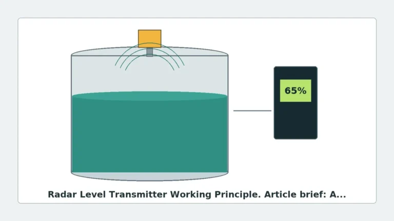
A radar level transmitter is an advanced sensing device that uses electromagnetic waves—specifically in the microwave frequency range—to determine the distance between the sensor and the surface of a liquid or solid medium. Unlike ultrasonic sensors, which rely on sound waves and are susceptible to air temperature and pressure changes, radar waves travel at the speed of light and are largely unaffected by the atmosphere within a tank.
1. Time of Flight (ToF)
The fundamental principle governing most radar transmitters is Time of Flight. The device emits a microwave signal toward the product surface. When the signal hits the medium, a portion of the energy is reflected back to the sensor. The transmitter measures the time interval between the emission and the reception. Since the speed of electromagnetic waves is constant ($c \approx 300,000$ km/s), the distance ($D$) is calculated as:
$$D = \frac{c \times t}{2}$$
Where $t$ is the total travel time. By subtracting this distance from the known height of the tank, the level of the medium is determined.
2. Frequency Modulated Continuous Wave (FMCW)
While pulse radar sends discrete bursts, modern high-precision instruments often use Frequency Modulated Continuous Wave (FMCW) technology. In FMCW, the transmitter emits a continuous signal with a constantly changing frequency (a frequency sweep). The reflection from the product surface is received and compared to the signal being emitted at that exact moment. The difference in frequency (the "beat frequency") is directly proportional to the distance. FMCW is preferred for high-accuracy applications, particularly with 80GHz technology, as it provides superior signal-to-noise ratios.
3. Guided Wave Radar (GWR) vs. Non-Contact Radar
It is important to distinguish between the two primary physical configurations:
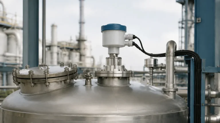
* Non-Contact Radar: The antenna is mounted at the top of the vessel and transmits waves through the air/gas space. It is ideal for corrosive or extremely hot materials where physical contact is undesirable.
* Guided Wave Radar (GWR): The microwave signal travels along a physical probe (rod or cable) immersed in the medium. GWR is highly effective for low-dielectric liquids and interface measurements (e.g., the boundary between oil and water).
Technical Selection Criteria for Industrial Applications
Choosing the right radar level transmitter requires an analysis of the medium's properties and the physical constraints of the vessel. The following table provides a comparison of common radar frequencies used in industrial Radar Level Meters.
Table 1: Radar Frequency Comparison
| Feature | 6.3 GHz (C-Band) | 26 GHz (K-Band) | 80 GHz (W-Band) |
| :— | :— | :— | :— |
| Beam Angle | Wide (approx. 20-30°) | Medium (approx. 8-12°) | Narrow (approx. 3-4°) |
| Accuracy | ±10 mm to ±20 mm | ±2 mm to ±5 mm | ±1 mm |
| Dust/Steam Resistance | Excellent | Good | Moderate (requires lens cleaning) |
| Antenna Size | Large | Medium | Small/Compact |
| Best Use Case | Heavy turbulence, thick foam | Standard process tanks | Tall, narrow silos; internal obstructions |
Dielectric Constant ($ε_r$)
The dielectric constant of the material is perhaps the most critical factor. Radar waves reflect best off materials with high conductivity or high dielectric constants (e.g., water, $ε_r ≈ 80$). Materials with low dielectric constants (e.g., hydrocarbons, solvents, $ε_r < 2.0$) reflect very little energy. In these cases, high-sensitivity 80GHz transmitters or Guided Wave Radar are often required to ensure a reliable signal return.
Installation Considerations and Best Practices
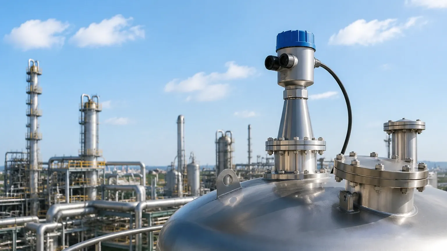
Even the most advanced radar level transmitter will fail if installed incorrectly. Engineers must account for the physical geometry of the tank and the behavior of the microwave beam.
1. Nozzle Geometry
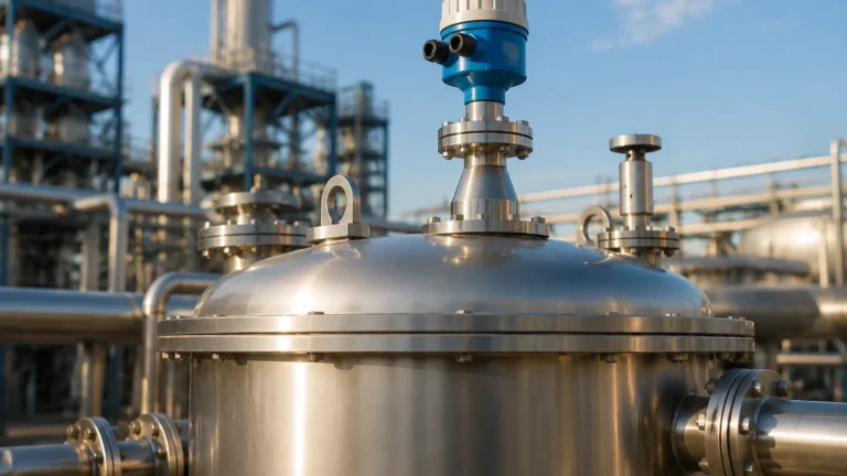
The mounting nozzle should be as short and wide as possible. If a nozzle is too long or narrow, the radar signal may reflect off the internal walls of the nozzle before even entering the tank, creating "ringing" or false echoes that mask the true level near the top of the vessel (the "Dead Zone").
2. Avoiding Obstructions
The radar beam spreads as it travels. Any internal structures within this beam—such as ladders, heating coils, agitators, or support struts—will create false reflections.
* Clearance: Maintain a minimum distance from the tank wall (typically 200mm to 500mm depending on height) to avoid interference.
* False Signal Suppression: Modern transmitters allow for "echo mapping," where the software is taught to ignore static reflections from internal tank hardware.
3. Beam Angle and Orientation
The beam angle is defined as the point where the signal power drops to half (-3dB). A narrower beam (high frequency) is easier to aim away from obstructions. For solid materials, which often form a conical heap, the transmitter may need to be mounted on a swiveling flange to aim the beam perpendicular to the slope of the material for maximum signal return.
Limitations and Application Risks
While radar is highly versatile, it is not a "one-size-fits-all" solution. Understanding its limitations is key to avoiding process downtime.
* Heavy Foam: While radar can penetrate some light foam, thick, dense foam (like shaving cream) can absorb or scatter the radar signal entirely. In such cases, GWR or hydrostatic pressure sensors might be more reliable.
* Vapor and Condensation: While microwaves pass through most vapors, extreme pressure and specific gas compositions (like high-pressure CO2) can slow the signal, leading to measurement errors. Condensation on the antenna lens can also attenuate the signal; using PTFE-coated drop antennas can help shed droplets.
* Turbulence: Rapidly moving liquid surfaces can scatter the signal. This is usually mitigated by increasing the damping (averaging) time in the transmitter settings or using a stilling well.
FAQ: Guidance for International Procurement and Engineering
Q: How do I choose between 26GHz and 80GHz for a new installation?
A: 26GHz is a cost-effective workhorse for standard tanks. Choose 80GHz if you have a very tall silo (over 30 meters), narrow nozzles, or many internal obstructions that require a pinpoint beam. 80GHz is also superior for measuring materials with very low dielectric constants.
Q: Can radar level transmitters be used in vacuum or high-pressure tanks?
A: Yes. Because radar does not require a medium for wave propagation (unlike ultrasonic), it functions perfectly in a vacuum. High-pressure versions are available, often rated up to 40 MPa (400 Bar) or higher, provided the process seal is appropriately specified.
Q: What maintenance is required for these instruments?
A: Radar transmitters are generally low-maintenance because they have no moving parts. However, in dusty or crystallizing environments, the antenna should be inspected periodically for buildup. Many units now feature air-purge connections to automatically clean the antenna face.
Q: Is it necessary to empty the tank to calibrate a radar transmitter?
A: No. Most modern Radar Level Meters can be calibrated via software using the tank height and the distance to the product. This "dry calibration" is a significant advantage over technologies that require a full-to-empty cycle.
Summary for the B2B Buyer
When asking what is radar level transmitter technology's value proposition, the answer lies in its reliability under extreme conditions. For an international buyer or project engineer, the focus should be on providing the manufacturer with accurate process data: the chemical composition of the medium, the dielectric constant, the maximum temperature and pressure, and a detailed drawing of the tank internals.
Welk provides a range of radar solutions tailored to these specific industrial needs, from cost-effective 26GHz units for water treatment to high-precision 80GHz FMCW systems for complex chemical reactors. By understanding the physics of the measurement and the constraints of the installation environment, engineers can ensure long-term accuracy and safety in their level control loops.