C Ultrasonic Sensor
C Ultrasonic Sensor
In the landscape of industrial automation and process control, the demand for non-contact level measurement has grown exponentially. Among the various technologies available, the c ultrasonic sensor—often characterized by its compact design and integrated electronics—has emerged as a versatile solution for liquid and solid level monitoring. This guide provides a comprehensive technical overview of ultrasonic technology, selection criteria, and practical installation strategies for engineering professionals.
Understanding the Measurement Principle
Before selecting or installing an ultrasonic instrument, it is essential to understand the physical principles that govern its operation. Ultrasonic level meters operate on the "Time-of-Flight" (ToF) principle.
The Time-of-Flight Mechanism
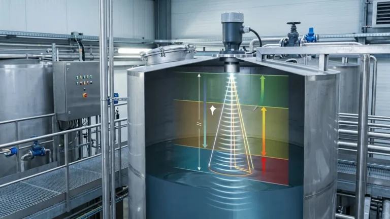
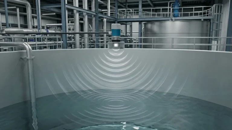
The sensor's transducer emits a high-frequency acoustic pulse, typically in the range of 20 kHz to 80 kHz. This sound wave travels through the air, reflects off the surface of the medium (liquid or solid), and returns to the transducer. The instrument's internal microprocessor measures the time interval between the emission of the pulse and the reception of the echo.
The distance ($D$) from the sensor to the surface is calculated using the formula:
$$D = \frac{c \times t}{2}$$
Where:
* $c$ is the speed of sound in the medium (usually air).
* $t$ is the total travel time (round trip).
Since the total distance includes the trip to the surface and back, the result is divided by two. The level of the material in the tank is then determined by subtracting this distance from the total tank height (the calibration zero point).
The Role of Temperature Compensation
The speed of sound in air is not constant; it varies with temperature. At 0°C, the speed of sound is approximately 331.5 m/s, while at 20°C, it increases to approximately 343 m/s. To maintain accuracy, most Ultrasonic Level Meters include an integrated temperature sensor to automatically adjust the calculation based on ambient conditions within the vessel.
Key Features of the C Ultrasonic Sensor
The term "c ultrasonic sensor" typically refers to a category of compact, integrated sensors where the transducer and the signal processing electronics are housed in a single unit. These are distinct from remote-headed systems where the controller is mounted separately.
Integrated Design
Compact sensors are designed for ease of installation. They usually feature a threaded or flanged connection and provide a direct output (such as 4-20mA or RS485 Modbus) to a PLC or SCADA system. This eliminates the need for specialized coaxial cabling between a sensor head and a remote transmitter.
Material Compatibility
Industrial sensors are often constructed from chemically resistant materials. Common housing and transducer face materials include:
* Polypropylene (PP): Suitable for general water and mild chemical applications.
* PVDF (Kynar): Highly resistant to aggressive acids and bases.
* Stainless Steel (316L): Used for food-grade applications or high-pressure environments.
Practical Selection Table
Choosing the right sensor requires balancing range, environment, and accuracy. The following table outlines typical specifications for standard industrial configurations.
| Feature | Short-Range (Compact) | Mid-Range (Standard) | Long-Range (Industrial) |
| :— | :— | :— | :— |
| Measuring Range | 0.25m – 5m (0.8ft – 16.4ft) | 0.4m – 12m (1.3ft – 39.4ft) | 0.6m – 30m (2ft – 98.4ft) |
| Frequency | 60 kHz – 80 kHz | 40 kHz – 50 kHz | 20 kHz – 30 kHz |
| Beam Angle | 6° – 8° | 10° – 12° | 12° – 15° |
| Accuracy | ±0.2% of span | ±0.25% of span | ±0.5% of span |
| Typical Application | Small chemical tanks, sumps | Water reservoirs, silos | Large bulk solids, deep wells |
Installation Considerations
The performance of a c ultrasonic sensor is heavily dependent on its physical placement. Poor installation is the leading cause of signal loss and measurement errors.
The Dead Zone (Blanking Distance)
Every ultrasonic sensor has a "dead zone" or "blanking distance" immediately in front of the transducer face. In this region, the transducer is still vibrating from the pulse emission and cannot yet act as a receiver. If the liquid level enters this zone, the sensor will provide an erratic or "frozen" reading.
* Guideline: Ensure the maximum high-level of the medium remains at least 10% further away than the specified dead zone.
Beam Angle and Obstructions
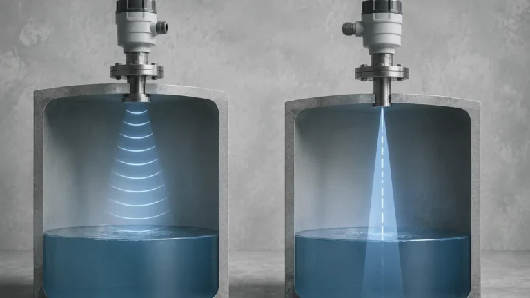
The ultrasonic pulse spreads out in a cone shape. Any internal tank structures—such as ladders, pipes, or agitators—that intersect this cone will create "false echoes."
* The 1/6 Rule: A general rule of thumb is to mount the sensor at a distance from the tank wall equal to at least 1/6 of the tank height to avoid wall interference.
* Perpendicularity: The sensor face must be perfectly parallel to the surface of the medium. Even a few degrees of tilt can cause the echo to bounce away from the receiver, especially on liquid surfaces.
Avoiding the Fill Stream
Never mount a sensor directly above the inlet flow. The falling liquid or solids will intercept the ultrasonic pulse, leading to false high-level readings or complete signal loss.

Limitations and Environmental Factors
While highly effective, ultrasonic technology is not a universal solution. Engineers must be aware of the following limitations:
1. Vacuum Conditions: Sound requires a medium (air or gas) to travel. Ultrasonic sensors cannot function in a vacuum.
2. Heavy Foam: Thick, protein-based foam can absorb the acoustic signal rather than reflecting it. In these cases, a radar level meter or a contact-based solution may be required.
3. High Dust and Vapor: While mild dust is manageable, extremely dense dust or heavy steam can attenuate the signal. Lower frequency sensors (long-range models) perform better in these conditions because their longer wavelengths can penetrate particulate matter more effectively.
4. Pressure Extremes: Standard ultrasonic sensors are typically rated for atmospheric pressure or slight overpressure (up to 3 bar / 43.5 psi). High-pressure applications can alter the density of the air, affecting the speed of sound beyond the capabilities of standard compensation algorithms.
Common Applications for C Ultrasonic Sensors
Water and Wastewater Treatment
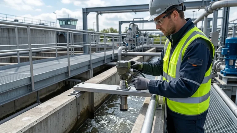
Ultrasonic sensors are the industry standard for monitoring open-channel flow (using flumes or weirs) and measuring levels in wet wells, pump stations, and chemical dosing tanks. Their non-contact nature prevents fouling from sewage or corrosive chemicals.
Chemical Processing
For storage tanks containing acids, bases, or solvents, a c ultrasonic sensor with a PVDF housing provides a maintenance-free alternative to mechanical floats or pressure transmitters that might corrode over time.
Food and Beverage
In many food processing applications, hygiene is paramount. Non-contact sensors eliminate the risk of contamination associated with probes that enter the product. Stainless steel housings with sanitary tri-clamp fittings are commonly used in these environments.
Frequently Asked Questions (FAQ)
Q: Can I use an ultrasonic sensor to measure the level of solids like sand or grain?
A: Yes. However, keep in mind that solids do not have a flat surface. They form cones (repose angles) which scatter the sound waves. You generally need a sensor with a higher power output and a wider beam to reliably track solid levels.
Q: How do I handle a tank with an agitator?
A: Most modern Ultrasonic Level Meters include "False Echo Suppression" software. During commissioning, you can map the tank while it is empty. The sensor identifies the static echoes from the agitator blades and ignores them during operation.
Q: What is the maximum cable length for a compact sensor?
A: For sensors with a 4-20mA output, the cable can typically run up to 1,000 meters (3,280 ft), provided the loop resistance is within the sensor's specifications. For RS485/Modbus, the limit is generally 1,200 meters (3,937 ft) without a repeater.
Q: Does wind affect the measurement?
A: In outdoor applications, strong winds can "blow" the acoustic pulse away, causing intermittent signal loss. Using a stilling well (a vertical pipe) can shield the pulse and provide a stable reading in windy or turbulent conditions.
Maintenance and Calibration
One of the primary advantages of the c ultrasonic sensor is the lack of moving parts, which minimizes maintenance. However, periodic checks are recommended:
* Transducer Cleaning: In high-moisture or dusty environments, condensation or buildup may occur on the transducer face. Wipe it periodically with a soft cloth and mild detergent.
* Calibration Verification: Verify the zero and span settings annually using a manual tape measure to ensure the sensor's internal temperature compensation is still accurate.
By understanding the acoustic principles and following strict installation guidelines, the c ultrasonic sensor provides a reliable, cost-effective, and low-maintenance solution for a wide array of industrial level measurement challenges.