Ultrasonic R
Ultrasonic R
In industrial process automation, the accuracy of liquid and solid level monitoring depends heavily on the physics of wave propagation. Among the various non-contact technologies available, Ultrasonic Level Meters remain a cornerstone for water treatment, chemical processing, and general industrial storage. A critical aspect of applying this technology effectively involves understanding "ultrasonic r"—the relationship between Range (R), Reflection, and Reliability.
This guide provides a comprehensive technical overview of how ultrasonic energy is used to determine levels, the variables that define the effective range of a sensor, and the practical engineering considerations required to ensure high-performance measurement in challenging environments.
The Fundamental Principle of Ultrasonic Measurement
Before selecting a specific instrument, it is essential to understand the Time-of-Flight (ToF) principle that governs these devices. An ultrasonic level meter consists of a transducer that acts as both a transmitter and a receiver.
Time-of-Flight (ToF) Mechanics
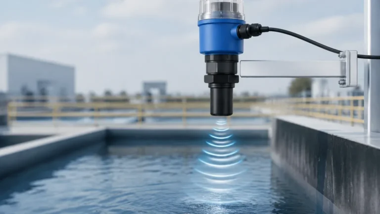
The transducer emits a series of high-frequency sound pulses (typically between 20 kHz and 200 kHz). These pulses travel through the air space above the medium, reflect off the surface of the material, and return to the transducer. The instrument measures the time interval between the emission of the pulse and the reception of the echo.
The distance (D) from the sensor to the surface is calculated using the formula:
D = (c × t) / 2
Where:
* c is the speed of sound in the medium (usually air).
* t is the measured time-of-flight.
The level (L) of the tank is then determined by subtracting the distance (D) from the total height of the vessel (H).
The Role of the Transducer
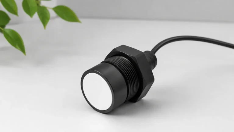
The transducer uses piezoelectric crystals to convert electrical energy into mechanical vibrations (sound waves) and vice versa. The efficiency of this conversion, combined with the frequency of the pulse, determines the "ultrasonic r" or effective range and resolution of the device. Higher frequencies provide better resolution but have a shorter range due to higher atmospheric attenuation, whereas lower frequencies can penetrate further but may struggle with smaller targets or precision in shallow tanks.
Understanding "Ultrasonic R": Range and Reflection Dynamics
In technical specifications, the "R" often refers to the maximum measuring range. However, for a professional engineer, the range is not a static number; it is a variable influenced by the reflection characteristics of the target material and the environment.
The Dead Zone (Blocking Distance)
Every ultrasonic sensor has a minimum range, often called the "dead zone" or "blocking distance." This is the area immediately in front of the transducer where the device cannot accurately measure because the crystal is still vibrating from the transmission phase when the echo returns. If the liquid level enters this zone, the meter will provide an error or an incorrect reading. Typical dead zones range from 0.2 meters to 0.6 meters depending on the frequency.
Signal Reflection and Surface Conditions
The reliability of the measurement depends on the strength of the reflected signal.
* Liquid Surfaces: Calm liquids act like mirrors, reflecting the signal directly back to the sensor. However, turbulence or waves can scatter the signal, reducing the effective range.
* Solid Materials: Granular solids (like grain or plastic pellets) often have an angle of repose. The ultrasonic pulse may reflect away from the sensor rather than back to it. In these cases, the effective "ultrasonic r" is significantly reduced, often requiring a sensor rated for twice the actual distance needed.
* Foam: Foam is a significant inhibitor. Depending on the density and thickness of the foam, it may either absorb the sound pulse entirely or reflect it prematurely, leading to false high-level readings.
Selection Criteria for Ultrasonic Level Meters
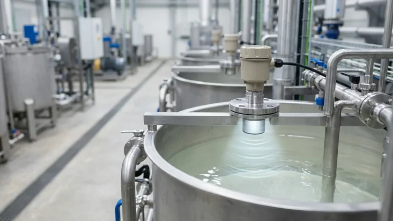
Choosing the right instrument requires balancing the physical constraints of the tank with the chemical properties of the medium. When evaluating Ultrasonic Level Meters, consider the following technical parameters:
1. Measuring Range
Match the sensor's maximum range to the tank height, but always include a safety margin. For liquids, a 10-20% margin is standard. For solids or dusty environments, a 50% margin is often necessary to compensate for signal attenuation.
2. Beam Angle
The beam angle defines the spread of the ultrasonic pulse. A narrower beam angle (e.g., 5° to 10°) is preferable for tall, narrow silos or tanks with internal obstructions like ladders or agitators. A wider beam may result in "false echoes" from the tank walls.
3. Temperature and Pressure
The speed of sound changes with air temperature (approximately 0.17% per degree Celsius). Professional meters include integrated temperature sensors to compensate for this. However, ultrasonic technology is generally limited to near-atmospheric pressure, as high pressure significantly alters the density of the air, affecting wave propagation.
4. Output and Communication
Standard industrial outputs include 4-20mA (analog) and RS485 (Modbus). For modern automation, integration with HART or Profibus may be required for remote diagnostics and configuration.
Technical Selection Table
The following table provides a general guideline for selecting a Welk ultrasonic level instrument based on common application profiles.
| Application Type | Typical Range (m) | Recommended Frequency | Key Consideration |
| :— | :— | :— | :— |
| Small Chemical Tank | 0.25 – 5m | 60 – 80 kHz | Chemical compatibility of the transducer face (PVDF/PTFE). |
| Open Channel Flow | 0.3 – 10m | 40 – 50 kHz | High accuracy and temperature compensation for outdoor use. |
| Large Water Reservoir | 0.5 – 20m | 20 – 30 kHz | High power output to overcome atmospheric humidity. |
| Solid Grain Silo | 0.6 – 15m | 20 kHz | Use of a self-cleaning transducer to prevent dust buildup. |
| Sump/Lift Station | 0.2 – 8m | 40 kHz | IP68 rating for potential submersion and condensation resistance. |

Installation Considerations for Maximum Signal Integrity
Proper installation is the most critical factor in ensuring the "ultrasonic r" meets the manufacturer's specifications. Even the most advanced sensor will fail if placed incorrectly.
Position and Orientation
1. Perpendicularity: The transducer face must be perfectly parallel to the liquid surface. A tilt of even a few degrees can cause the reflected signal to miss the receiver, especially at longer distances.
2. Avoid the Center: In cylindrical tanks with domed tops, do not install the sensor in the exact center. This can create a parabolic effect that amplifies unwanted echoes. Position the sensor at 1/2 or 1/3 of the tank radius.
3. Clear Path: Ensure the "signal cone" is free of obstructions. This includes fill streams, pipes, and internal supports. If an obstruction is unavoidable, many modern meters offer "false echo suppression" software to ignore static reflections.
Mounting Nozzles
If the sensor is mounted on a nozzle (standpipe), the nozzle must be as short and wide as possible. If the nozzle is too long or narrow, the ultrasonic pulse will bounce off the interior of the pipe before reaching the tank, creating a massive dead zone and signal interference.
Limitations and Environmental Challenges
While ultrasonic technology is versatile and cost-effective, it is not a universal solution. Engineers must be aware of the following limitations:
* Vacuum Conditions: Sound cannot travel in a vacuum. Ultrasonic meters will not work in full vacuum tanks.
* Vapor and Gas Layers: If the tank contains heavy vapors or gas layers (like high concentrations of CO2 or methane), the speed of sound will differ significantly from air. Unless the meter is calibrated for that specific gas mixture, the readings will be inaccurate.
* High Temperature: Most ultrasonic transducers are limited to operating temperatures below 80°C (176°F). Above this, the piezoelectric components and the housing materials may degrade.
* Heavy Dust: While some dust is manageable, extremely heavy dust clouds (common during pneumatic filling of silos) can absorb the ultrasonic energy, leading to a loss of signal.
Frequently Asked Questions (FAQ)
Q: Can ultrasonic level meters measure through a closed plastic tank lid?
A: Generally, no. The signal reflects off the first solid surface it hits. To measure through a lid, the material must be very thin and the sensor must be specifically designed for "through-wall" measurement, which is rare in industrial level sensing. Standard practice is to install a bulkhead fitting or a cut-out.
Q: How do I handle foam on the liquid surface?
A: Light, thin foam may be penetrated. However, thick, protein-based foam (like in a brewery) or heavy chemical foam will absorb the signal. In these cases, a stilling well (a vertical pipe that breaks the foam) can be used, or a different technology like a magnetic level gauge or a radar level meter should be considered.
Q: What is the difference between an ultrasonic level transmitter and an ultrasonic level switch?
A: A transmitter provides a continuous measurement of the level (e.g., 0-100%), while a switch only provides a digital signal (on/off) when the level reaches a specific point. Transmitters are used for process control and inventory management, while switches are typically used for overfill protection or pump control.
Q: Does the color of the liquid affect the measurement?
A: No. Unlike optical or laser sensors, ultrasonic waves are unaffected by the color, transparency, or opacity of the medium.
Conclusion
Mastering the application of Ultrasonic Level Meters requires a balance of physics and practical engineering. By understanding the dynamics of "ultrasonic r"—specifically how range and reflection interact with the process environment—users can implement reliable, non-contact measurement solutions that reduce maintenance costs and improve process safety.
Whether monitoring a simple water tank or a complex chemical reactor, following strict installation guidelines and respecting the physical limits of sound propagation ensures that the instrument provides the accurate data necessary for modern industrial automation. For those requiring specific technical data or customized sensor configurations, consulting with a specialized manufacturer like Welk can help bridge the gap between theoretical range and real-world performance.