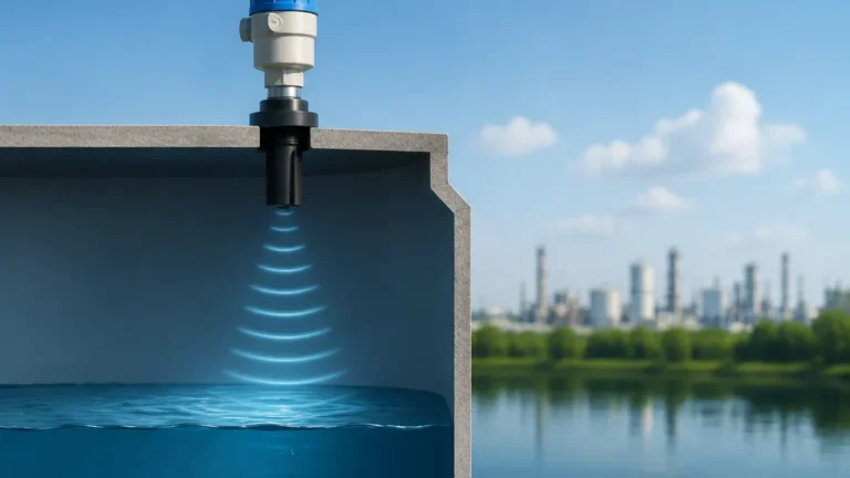
Ultrasonic Level Indicator Transmitter
Ultrasonic Level Indicator Transmitter: A Comprehensive Engineering Guide
In the landscape of industrial process control, the ability to monitor liquid and solid levels accurately without physical contact is a significant advantage. The ultrasonic level indicator transmitter has emerged as a cornerstone technology for these requirements. Combining local visualization with remote signal transmission, these devices provide real-time data essential for inventory management, process safety, and automation.
This guide explores the technical foundations, selection criteria, and practical installation strategies for Ultrasonic Level Meters to assist engineers and plant managers in optimizing their measurement systems.
Measurement Principles of Ultrasonic Level Indicator Transmitters
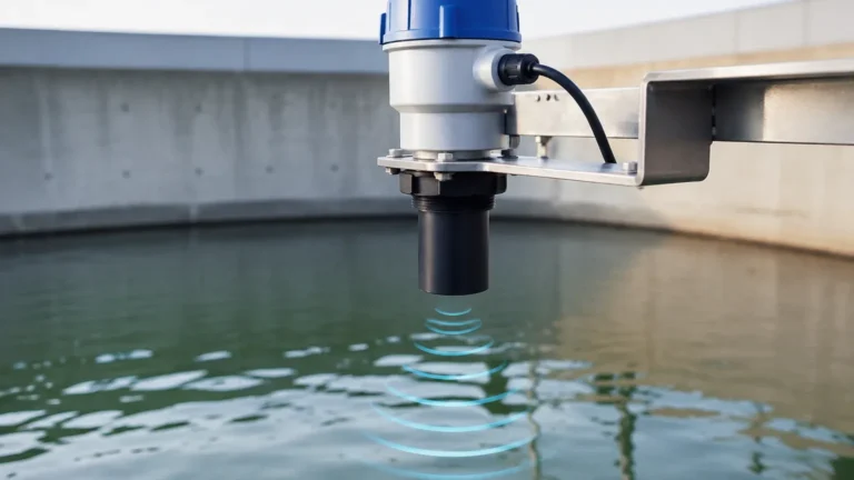
At its core, an ultrasonic level indicator transmitter operates on the "Time-of-Flight" (ToF) principle. The device features a transducer that acts as both a transmitter and a receiver of high-frequency sound waves, typically in the range of 20 kHz to 200 kHz.
The Time-of-Flight Calculation
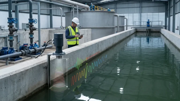
The transducer emits a pulse of ultrasonic energy toward the material surface. When the pulse hits the surface, it reflects back to the transducer. The transmitter's internal electronics measure the time interval between the emission of the pulse and the reception of the echo. The distance is calculated using the following formula:
D = (v × t) / 2
Where:
* D is the distance from the sensor to the material surface.
* v is the speed of sound in the medium (usually air).
* t is the total travel time of the pulse.
Since the total height of the tank (H) is known, the level (L) is determined by subtracting the measured distance from the total height: L = H – D.
Temperature Compensation
The speed of sound in air is approximately 331.5 m/s at 0°C, but it changes by roughly 0.6 m/s for every degree Celsius change in temperature. To maintain accuracy, a high-quality ultrasonic level indicator transmitter includes an integrated temperature sensor. This allows the device to automatically compensate for fluctuations in the ambient air temperature within the tank or vessel, ensuring the distance calculation remains precise despite environmental changes.
Key Features and Technical Specifications
Modern ultrasonic level indicator transmitters are designed to be robust and versatile. They often integrate several components into a single housing, including the acoustic transducer, the signal processing unit, and a digital display for local indication.
Integrated Indicator and Transmitter
The "indicator" aspect refers to the local LCD or LED display that allows operators to read levels directly at the measurement site. The "transmitter" aspect refers to the device's ability to convert the level reading into a standardized electronic signal—typically a 4-20mA analog output, often with HART protocol, or digital outputs like RS485 (Modbus).
Technical Parameters to Consider
* Measuring Range: Standard industrial units typically cover ranges from 0.25 meters (approx. 0.8 ft) up to 40 meters (approx. 131 ft).
* Accuracy: Most professional-grade sensors offer an accuracy of ±0.25% to ±0.5% of the full measured range.
* Beam Angle: Usually between 5° and 12°. A narrower beam angle is preferable for tall, narrow tanks to avoid interference from internal structures.
* Enclosure Rating: For outdoor or wash-down environments, IP66 or IP67 ratings are standard, with IP68 available for submersible applications.
Selection Criteria for Engineering Projects
Selecting the correct ultrasonic level indicator transmitter requires a detailed understanding of the application environment. Not all ultrasonic sensors are suitable for every liquid or solid.
Practical Selection Table
| Application Type | Recommended Range | Key Feature Required | Typical Output |
| :— | :— | :— | :— |
| Water Storage Tanks | 0-10m (0-33ft) | Standard IP67 Housing | 4-20mA |
| Chemical Processing | 0-5m (0-16ft) | PTFE/PVDF Wetted Parts | 4-20mA + HART |
| Open Channel Flow | 0-2m (0-6.5ft) | High Resolution/Accuracy | RS485 Modbus |
| Solids/Powders | 0-15m (0-49ft) | High Power Transducer | 4-20mA |
| Wastewater Sumps | 0-8m (0-26ft) | Submersible IP68 Rating | 4-20mA |
Material Compatibility
For corrosive environments, such as acid or alkali storage, the transducer face must be constructed from chemically resistant materials. While standard transducers use ABS or PVC, specialized units utilize PVDF (Polyvinylidene Fluoride) or PTFE (Polytetrafluoroethylene) to prevent degradation.
Installation Guidelines and Best Practices
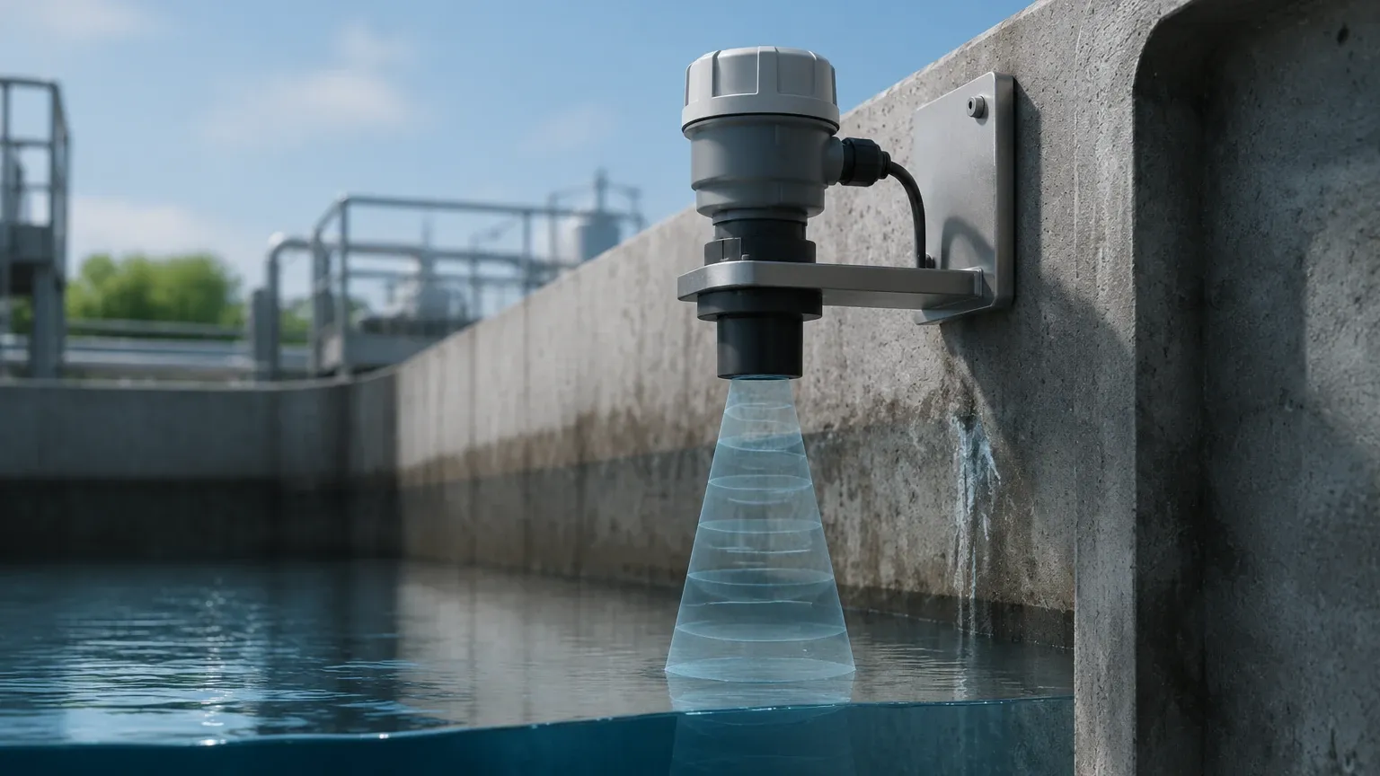
Proper installation is the most critical factor in ensuring the reliability of an ultrasonic level indicator transmitter. Because the technology relies on sound waves, physical obstructions and vessel geometry can significantly impact performance.
Avoiding the "Dead Zone"
Every ultrasonic sensor has a "dead zone" (also known as the blocking distance) directly beneath the transducer face, typically ranging from 0.2m to 0.6m (8 to 24 inches). The sensor cannot accurately measure any material that enters this zone. Engineers must mount the sensor high enough so that the maximum expected liquid level never enters the dead zone.
Mounting Position
* Avoid the Center: In cylindrical tanks with domed tops, do not mount the sensor in the exact center. This can create a parabolic effect, focusing multiple echoes back to the sensor and causing erratic readings.
* Stay Away from Inlets: Do not install the sensor near the fill pipe. Falling liquid or solids create turbulence and noise that interfere with the ultrasonic pulse.
* Perpendicular Alignment: The transducer face must be perfectly horizontal and perpendicular to the liquid surface to ensure the echo returns directly to the receiver.
Beam Path Obstructions
The ultrasonic beam spreads as it travels. Ensure the path is clear of internal ladders, heating coils, or agitators. If an obstruction is unavoidable, many modern transmitters offer "false echo suppression" software, allowing the user to program the device to ignore specific static reflections.
Limitations and Environmental Challenges
While highly effective, ultrasonic technology has physical limitations that must be acknowledged during the design phase.
1. Vacuum Conditions: Ultrasonic waves require a medium (gas/air) to travel. Therefore, they cannot function in a vacuum.
2. Heavy Foam: Thick, dense foam on the surface of a liquid acts as an acoustic absorber. It soaks up the ultrasonic pulse rather than reflecting it, leading to a "loss of echo" error.
3. High Pressure and Temperature: Extreme pressure changes the density of the air, affecting the speed of sound beyond what standard temperature compensation can handle. Most ultrasonic level indicator transmitters are limited to near-atmospheric pressure.
4. Heavy Dust or Steam: While light dust is manageable, extremely heavy dust (in grain silos) or dense steam can attenuate the signal, reducing the effective measuring range.
Maintenance and Troubleshooting FAQ
How often should I calibrate my ultrasonic transmitter?
In stable environments, annual verification is usually sufficient. However, if the medium emits vapors that could coat the transducer face, more frequent inspections are recommended to ensure no buildup is dampening the signal.
What causes a "Loss of Echo" (LOE) signal?
LOE typically occurs due to heavy foam, extreme turbulence, or the material level entering the dead zone. It can also happen if the transducer is not mounted perpendicular to the surface, causing the echo to bounce away from the sensor.
Can I use an ultrasonic level indicator transmitter for solids?
Yes, but with caveats. Solids like plastic pellets or grains do not form a flat reflective surface like liquids. Instead, they form a conical pile. This scatters the sound waves, effectively reducing the measurable range by about 50%. For solids, always select a sensor with a higher power rating than the actual distance requires.
How do I handle condensation on the sensor face?
Condensation can cause the sensor to "lock" on a high-level reading. Selecting a transmitter with a self-cleaning transducer face or a higher-frequency vibration pulse can help shed water droplets and maintain a clear signal.
For technical assistance in selecting the right configuration for your facility, you can Review product options and application support to find a solution tailored to your specific industrial requirements.