Ultrasonic Level Sensor Frequency
Understanding Ultrasonic Level Sensor Frequency: A Technical Guide for Industrial Applications
In industrial process control, selecting the correct instrumentation is a balance between precision, range, and environmental resilience. For non-contact liquid and solid level measurement, Ultrasonic Level Meters remain a cornerstone technology due to their cost-effectiveness and reliability. However, the performance of these devices is fundamentally dictated by one physical parameter: the ultrasonic level sensor frequency.
The frequency at which a transducer operates determines how far the signal can travel, how well it can penetrate dust or steam, and how narrow the measurement beam will be. For engineers and procurement specialists at Welk and across the industrial automation sector, understanding the relationship between frequency and application requirements is essential for ensuring long-term operational accuracy.
The Principle of Ultrasonic Level Measurement
Before delving into the specifics of frequency, it is necessary to understand the underlying measurement principle. Ultrasonic level sensors operate on the "Time of Flight" (ToF) principle.
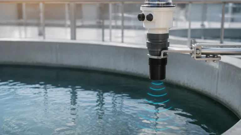
The sensor’s transducer acts as both a transmitter and a receiver. It emits a high-frequency acoustic pulse that travels through the air (or headspace gas) until it strikes the surface of the medium (liquid or solid). A portion of this sound energy is reflected back to the sensor as an echo. By measuring the time interval between the emission of the pulse and the reception of the echo, the device calculates the distance to the surface using the speed of sound in the medium.
Distance is calculated using the formula:
D = (c × t) / 2
Where:
* D is the distance to the surface.
* c is the speed of sound in the headspace (approximately 343 m/s in air at 20°C).
* t is the total travel time of the pulse.
The frequency of this acoustic pulse—the ultrasonic level sensor frequency—is the primary variable that determines the sensor's physical capabilities.
The Relationship Between Frequency, Range, and Accuracy
In the world of acoustics, there is an inverse relationship between frequency and the distance a wave can travel before it loses its energy. This phenomenon, known as atmospheric attenuation, is the primary reason why ultrasonic sensors are offered in various frequency ratings, typically ranging from 20 kHz to over 70 kHz.
1. Low Frequency (20 kHz to 30 kHz)
Low-frequency sensors produce longer wavelengths. These waves are more robust and less susceptible to attenuation by the atmosphere.
* Range: These are designed for long-range applications, often capable of measuring distances up to 30 meters (approx. 100 ft) or even 40 meters in ideal conditions.
* Penetration: Low frequencies can better bypass obstacles like heavy dust, steam, or light foam. The larger wavelength can "wrap around" small particles rather than being scattered by them.
* Beam Angle: Generally, lower frequency transducers have a wider beam angle, which requires a larger clear path within the tank to avoid false reflections from walls or internal structures.
2. High Frequency (50 kHz to 70 kHz+)
High-frequency sensors produce shorter wavelengths, which offer higher resolution but are more easily absorbed by the air.
* Range: These are typically used for short to medium ranges, usually capped at 5 to 10 meters (16 to 33 ft).
* Precision: Shorter wavelengths allow for much higher measurement resolution and accuracy, often within ±2 mm.
* Beam Angle: High-frequency transducers can be engineered with much narrower beam angles (often 5° to 8°), making them ideal for narrow tanks or vessels with internal agitators and ladders.
Impact of Frequency on Beam Angle and Installation
The ultrasonic level sensor frequency directly influences the beam spread. A common challenge in industrial silos and tanks is the presence of internal obstructions. If the ultrasonic beam is too wide, it may hit a pipe, a ladder, or a weld seam before it reaches the liquid surface, resulting in a false high-level reading.
* Narrow Beams (High Frequency): By utilizing a higher frequency, manufacturers like Welk can produce sensors that focus the energy into a tight cone. This allows the sensor to be installed in smaller nozzles or closer to the tank wall.
* Wide Beams (Low Frequency): While lower frequencies are necessary for depth, they require a "clearance zone." If a 20 kHz sensor is used in a narrow 1-meter wide tank, the signal will likely bounce off the sides, creating noise and reducing accuracy.
Environmental Factors and Frequency Selection
The environment within the vessel often dictates the required frequency more than the range itself.
Dust and Vapor
In grain silos or cement storage, dust is a constant factor. High-frequency waves (shorter wavelengths) are easily scattered by dust particles. In these scenarios, a lower ultrasonic level sensor frequency (e.g., 20 kHz) is preferred because the longer wavelength can penetrate the dust cloud to reach the material surface.
Temperature and Pressure
The speed of sound changes with temperature. While most modern Ultrasonic Level Meters include integrated temperature compensation, extreme temperature gradients can cause signal refraction. High-frequency sensors are more sensitive to these atmospheric changes than low-frequency models.
Foam and Turbulence
Foam is the "enemy" of ultrasonic measurement because it absorbs the acoustic signal rather than reflecting it. If light foam is present, a lower frequency sensor with higher power output may be able to receive a return echo, whereas a high-frequency sensor would likely lose the signal entirely.

Practical Selection Table
The following table provides a general guideline for selecting the appropriate frequency based on common industrial application parameters.
| Application Type | Typical Range | Recommended Frequency | Key Advantage |
| :— | :— | :— | :— |
| Small Chemical Tanks | 0.25m – 5m | 60 kHz – 80 kHz | High precision, narrow beam for tight spaces. |
| Water/Wastewater Sumps | 0.5m – 10m | 40 kHz – 50 kHz | Balanced range and resolution; handles humidity well. |
| Large Liquid Storage | 1m – 15m | 30 kHz – 40 kHz | Reliable echo return over longer distances. |
| Solid Silos (Grain/Cement) | 2m – 30m | 20 kHz – 25 kHz | Penetrates dust; high power for uneven surfaces. |
| Open Channel Flow | 0.1m – 3m | 70 kHz+ | Maximum resolution for precise flow calculation. |
Installation Considerations and Limitations
Regardless of the frequency chosen, certain physical limitations of ultrasonic technology must be managed during installation.
The Blocking Distance (Dead Zone)
Every ultrasonic sensor has a "blocking distance" or "dead zone" directly in front of the transducer face. This is the distance the transducer needs to stop vibrating from the transmission pulse before it can begin listening for the echo.
* High-frequency sensors usually have smaller dead zones (e.g., 100 mm to 250 mm).
* Low-frequency sensors have larger dead zones (e.g., 400 mm to 800 mm) due to the longer vibration decay time of the larger transducer element.
Mounting Orientation
The sensor must be mounted perpendicular to the liquid surface. If the sensor is tilted, the reflected pulse may not return to the transducer, especially with high-frequency sensors that have narrow beam angles.
Vacuum and Pressure Limitations
Ultrasonic waves require a medium (gas) to travel. Therefore, ultrasonic level meters cannot function in a vacuum. Additionally, high-pressure environments increase the density of the gas, which can significantly alter the speed of sound and signal attenuation, often requiring specialized calibration or a shift to radar technology.
Frequently Asked Questions (FAQ)
Q: Can I use a high-frequency sensor for a 20-meter deep silo?
A: Generally, no. The signal attenuation at high frequencies (e.g., 60 kHz) is too great to provide a reliable echo return from 20 meters, especially if dust is present. A 20 kHz or 25 kHz sensor is required for this range.
Q: Does the frequency affect the sensor's ability to measure through a plastic tank wall?
A: No. Ultrasonic sensors (unlike some radar or capacitive sensors) cannot measure through tank walls. They require a clear path to the medium. If you must measure through a wall, the sensor must be specifically designed as a "clamp-on" ultrasonic sensor, which operates on different principles (ultrasonic coupling).
Q: Why is my sensor showing a full tank when it is actually empty?
A: This is often caused by "ringing" or reflections from a mounting nozzle. If the ultrasonic level sensor frequency is not matched with a proper dead zone setting or if the nozzle is too narrow and long, the sensor may detect the end of the nozzle as the liquid level.
Q: How does humidity affect different frequencies?
A: Humidity changes the density of the air, which affects the speed of sound. While it affects all frequencies, higher frequencies are slightly more susceptible to signal dampening in very high-humidity environments (90%+ RH).
Conclusion
Selecting the right ultrasonic level sensor frequency is a critical step in engineering a reliable level measurement system. By matching the frequency to the specific range, accuracy requirements, and environmental conditions of the application, operators can avoid common pitfalls like signal loss, false echoes, and poor resolution.
For most standard liquid applications, mid-range frequencies (40-50 kHz) offer the best versatility. However, for specialized tasks involving deep solids or high-precision chemical dosing, moving to the lower or higher ends of the frequency spectrum is necessary. As a professional manufacturer, Welk provides a comprehensive range of Ultrasonic Level Meters tailored to these diverse industrial needs, ensuring that whether you are managing water treatment or complex chemical processing, your measurements remain accurate and cost-effective.