Ultrasonic Level Sensor Bracket
Ultrasonic Level Sensor Bracket: A Comprehensive Engineering Guide to Installation and Selection
In the field of industrial process control, the accuracy of level measurement is fundamentally dependent on the physical stability and orientation of the sensing element. While the internal electronics and signal processing algorithms of Ultrasonic Level Meters have become increasingly sophisticated, the mechanical interface—specifically the ultrasonic level sensor bracket—remains a critical factor in system reliability.
This guide explores the technical principles of ultrasonic measurement, the functional requirements of mounting hardware, and the practical considerations necessary for selecting and installing brackets in diverse industrial environments.
Understanding the Measurement Principle
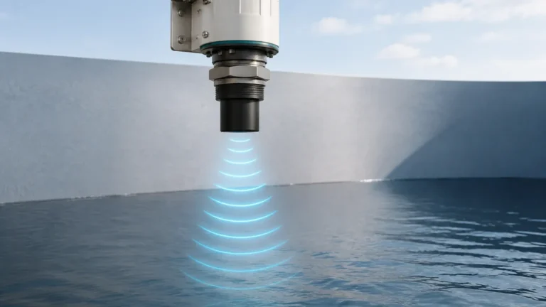
Before selecting an ultrasonic level sensor bracket, it is essential to understand how the instrument interacts with its environment. Ultrasonic level meters operate on the Time-of-Flight (ToF) principle. The sensor’s transducer emits a high-frequency acoustic pulse (typically between 20 kHz and 200 kHz) toward the surface of the material being measured.
1. Emission: The pulse travels through the air at the speed of sound.
2. Reflection: Upon hitting the liquid or solid surface, a portion of the sound energy is reflected back toward the sensor.
3. Detection: The transducer receives the echo, and the internal processor calculates the time elapsed between emission and reception.
The distance ($D$) is calculated using the formula:
$D = (v \times t) / 2$
where $v$ is the velocity of sound in the medium (adjusted for temperature) and $t$ is the transit time.
The Importance of Perpendicularity
Because sound waves follow the laws of reflection, the emitted pulse must strike the target surface at a 90-degree angle to ensure the maximum amount of energy returns to the transducer. If the sensor is tilted due to a poorly designed or improperly installed bracket, the signal may reflect away from the receiver, leading to "Loss of Echo" errors or erratic readings. A high-quality ultrasonic level sensor bracket provides the necessary rigidity to maintain this alignment despite wind, vibration, or thermal expansion.
The Critical Role of the Ultrasonic Level Sensor Bracket
A mounting bracket is not merely a piece of support hardware; it is a precision positioning tool. In B2B industrial applications—ranging from wastewater treatment plants to chemical storage facilities—the bracket serves several vital functions:
* Signal Alignment: Ensures the sensor face is perfectly parallel to the liquid surface.
* Vibration Isolation: Dampens mechanical vibrations from pumps or mixers that could interfere with the transducer’s sensitive piezo-elements.
* Environmental Protection: Offsets the sensor from tank walls or corrosive surfaces, extending the lifespan of the device.
* Maintenance Accessibility: Allows technicians to safely access the sensor for calibration or cleaning without entering confined spaces.
Types of Mounting Brackets and Hardware
Depending on the installation site—whether it is an open channel, a sump, or a closed tank—different bracket geometries are required.
1. L-Type Fixed Brackets
The most common variety, often made from stainless steel (SS304 or SS316). These are typically used for wall mounting over open sumps or flumes. They provide a fixed horizontal extension, ensuring the sensor is positioned away from the wall to avoid false reflections.
2. Adjustable Extension Arms
These brackets allow for horizontal and sometimes vertical adjustment. They are ideal for applications where the exact measurement point might need to be fine-tuned after installation to avoid internal obstructions like ladders or pipes.
3. Flange Adapters
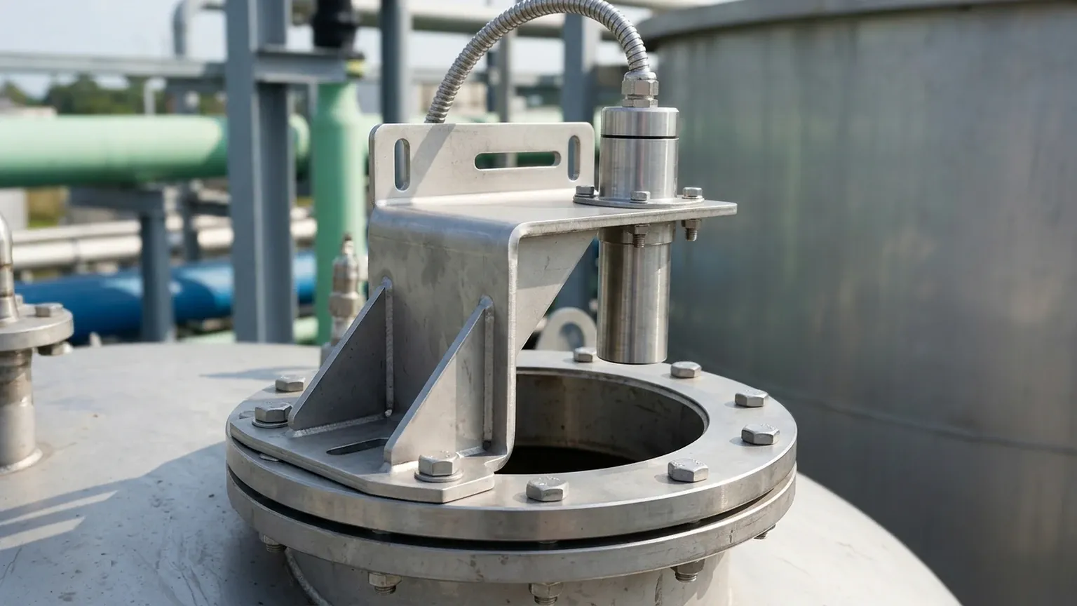
For closed vessels, a bracket may take the form of a flange adapter. While technically a fitting, it serves the same purpose as a bracket by securing the sensor to a nozzle. It is critical that these are designed to prevent the sensor face from being recessed too far into the nozzle, which can cause signal interference.
4. Bridge or Portal Mounts
Used in wide open channels or large reservoirs, these brackets span the width of the channel, allowing the ultrasonic level sensor to be positioned directly over the center of the flow.
Selection Criteria for Industrial Brackets
When specifying an ultrasonic level sensor bracket, engineers must evaluate the following criteria to ensure long-term performance:
| Criteria | Considerations | Recommended Specification |
| :— | :— | :— |
| Material | Resistance to corrosion and UV degradation. | SS316 for chemicals; Carbon steel with epoxy coating for general use; PVC/PP for highly acidic environments. |
| Rigidity | Ability to withstand wind loads (outdoor) and mechanical vibration. | Minimum 3mm to 5mm thickness for stainless steel arms. |
| Adjustability | Need for field alignment. | Multi-slot designs or swivel joints for non-level surfaces. |
| Dimensions | Extension length to clear the "Dead Zone" and wall interference. | Ensure the sensor is at least 200mm to 500mm (7.8" to 19.6") from the wall. |
| Mounting Interface | Compatibility with sensor threads. | Standard 1", 1.5", or 2" NPT/BSP thread holes. |
Installation Best Practices and Geometric Constraints
Proper installation of the bracket is as important as the quality of the Ultrasonic Level Meters themselves. Failure to adhere to geometric constraints is the leading cause of measurement failure.
1. Managing the Dead Zone
Every ultrasonic sensor has a "Dead Zone" (or Blanking Distance) directly beneath the transducer face where it cannot measure. This typically ranges from 200mm to 600mm (7.8" to 23.6") depending on the frequency. The bracket must be installed high enough so that the maximum liquid level never enters this zone.
2. Beam Angle and Obstructions
Ultrasonic pulses propagate in a cone shape, usually between 5° and 12°. The bracket must position the sensor so that this cone does not intersect with tank walls, ladders, or agitators. If the beam hits a wall, it will create a "fixed echo," which the sensor may mistake for the actual level.
* Rule of Thumb: For every 1 meter of depth, allow at least 10cm of clearance from the wall (approx. 1.2 inches of clearance per foot of depth).
3. Avoiding Turbulence and Foam
Brackets should be positioned away from inlet pipes where falling liquid creates turbulence or foam. Foam absorbs sound waves, significantly weakening the return echo. If turbulence is unavoidable, the bracket may need to support a stilling well (a vertical pipe that stabilizes the surface).
4. Outdoor Considerations
When using an ultrasonic level sensor bracket outdoors, thermal expansion of the bracket itself is negligible, but solar radiation can heat the sensor body. In extreme climates, a bracket with an integrated sunshade is recommended to prevent the internal temperature compensation of the sensor from being skewed by direct sunlight.
Common Challenges and Signal Interference
Even with a sturdy bracket, certain environmental factors can challenge ultrasonic measurement:
* Vapor and Condensation: In closed tanks, heavy vapors can change the speed of sound, while condensation on the transducer face can attenuate the signal. Brackets should be installed to allow a slight tilt (less than 1°) if it helps moisture run off the sensor face, though this is rarely recommended over a perfectly level installation.
* Heavy Dust: In solid level measurement, dust can coat the transducer. The bracket should be positioned to allow easy access for periodic cleaning.
* False Echoes from Brackets: If the bracket itself has protruding bolts or edges near the transducer face, these can create parasitic reflections. Ensure the mounting hole is clean and the sensor face extends slightly below the bottom of the bracket plate.
Maintenance and Long-term Reliability
Industrial environments are harsh. A maintenance schedule for mounting hardware should include:
* Structural Integrity Check: Inspecting the ultrasonic level sensor bracket for signs of stress corrosion cracking or rust, especially at weld points.
* Fastener Tightness: Ensuring that vibration hasn't loosened the bolts securing the bracket to the structure or the sensor to the bracket.
* Alignment Verification: Using a spirit level to confirm the sensor remains perpendicular to the target surface.
Frequently Asked Questions (FAQ)
Q: Can I fabricate my own ultrasonic level sensor bracket?
A: Yes, provided it meets the rigidity and material requirements. However, pre-engineered brackets often include slotted holes for easier alignment and are treated for specific environmental resistances, saving on-site labor costs.
Q: How far should the bracket extend from the wall?
A: This depends on the depth of the tank and the beam angle of your Ultrasonic Level Meters. Generally, the sensor should be placed at 1/4 to 1/3 of the tank diameter away from the wall to avoid interference while remaining accessible.
Q: What material is best for a bracket in a wastewater application?
A: Stainless steel 304 is usually sufficient for municipal wastewater, but 316 is preferred if there are high concentrations of H2S (Hydrogen Sulfide) or other corrosive gases.
Q: Does the bracket affect the accuracy of the sensor?
A: Indirectly, yes. If the bracket vibrates or allows the sensor to tilt, the accuracy and signal strength will degrade. A stable, level mount is a prerequisite for the accuracy specifications provided by the manufacturer.
Conclusion
Selecting the correct ultrasonic level sensor bracket is a foundational step in ensuring the success of any level measurement project. By understanding the acoustic principles of the sensor and the mechanical demands of the installation site, engineers can prevent the most common causes of signal failure. Whether utilizing standard L-brackets or custom-engineered mounting solutions, the goal remains the same: providing a stable, perpendicular, and accessible platform for the sensor to perform its critical function.
For high-performance applications, always pair your mounting hardware with robust Ultrasonic Level Meters designed for industrial rigors, ensuring a complete solution that delivers accurate data year after year.