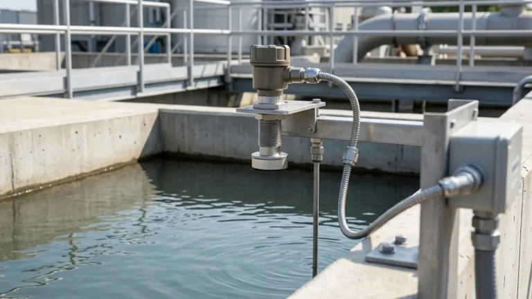
Ultrasonic Level Sensor Calibration
Ultrasonic Level Sensor Calibration: A Practical Industrial Guide
In industrial process automation, the accuracy of level measurement is fundamental to operational safety, inventory management, and process efficiency. Among the various technologies available, Ultrasonic Level Meters have become a standard choice for non-contact measurement in water treatment, chemical processing, and general industrial applications. However, the reliability of these instruments depends heavily on precise ultrasonic level sensor calibration and a deep understanding of the environmental variables that influence sound propagation.
This guide provides a comprehensive overview of the principles behind ultrasonic measurement, the technical steps required for calibration, and the practical considerations necessary to ensure long-term accuracy in demanding B2B environments.
Understanding the Measurement Principle
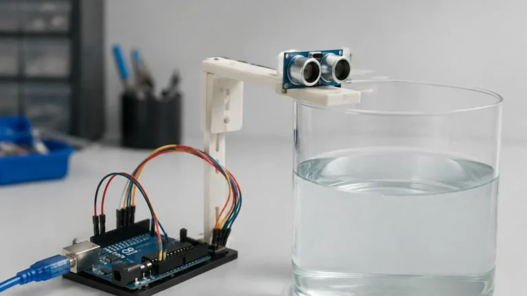
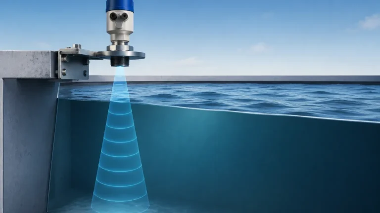
Before initiating the calibration process, it is essential to understand the physics of ultrasonic technology. Ultrasonic sensors operate on the "Time-of-Flight" (ToF) principle. The sensor’s transducer contains a piezoelectric crystal that converts electrical energy into high-frequency sound pulses. These pulses travel through the air, reflect off the surface of the medium (liquid or solid), and return to the transducer.
The distance ($D$) between the sensor and the material surface is calculated using the formula:
$$D = \frac{c \times t}{2}$$
Where:
- $c$ is the speed of sound in the medium (typically air).
- $t$ is the total time elapsed between the emission of the pulse and the reception of the echo.
Because the speed of sound in air is approximately 343 meters per second (m/s) at 20°C but fluctuates with temperature, humidity, and atmospheric pressure, the calibration process must account for these variables to convert a raw time measurement into a precise level reading.
The Importance of Ultrasonic Level Sensor Calibration
While most Ultrasonic Level Meters are shipped with factory default settings, "out-of-the-box" accuracy is rarely sufficient for specific industrial vessels. Calibration is the process of mapping the sensor's electronic output (typically a 4-20mA signal or a digital protocol like HART or Modbus) to the physical dimensions of the tank or silo.
Effective calibration ensures:
1. Zero-Point Accuracy: Establishing exactly where the "empty" state is relative to the sensor face.
2. Span Accuracy: Defining the "full" state and ensuring the sensor scales linearly between empty and full.
3. Volume Conversion: Translating linear distance into volume (liters, cubic meters, or gallons) for non-linear vessels like horizontal cylindrical tanks.
4. Environmental Compensation: Adjusting for the specific gas composition and temperature profile within the headspace of the tank.
Step-by-Step Calibration Procedure
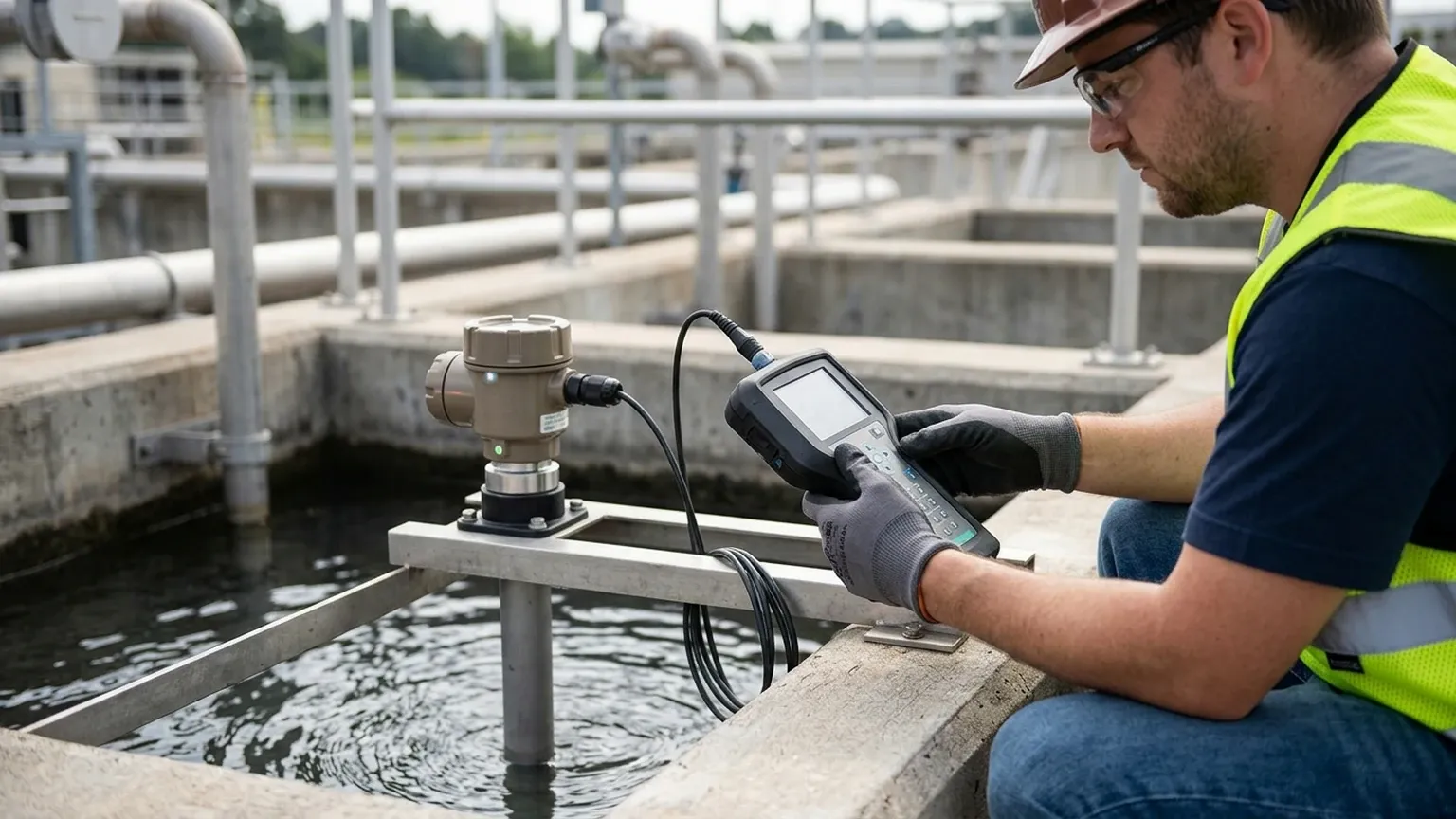
Calibration can be performed via the instrument’s local display interface, a handheld programmer, or specialized PC software. Regardless of the interface, the following steps are standard for industrial applications.
1. Setting the Empty Distance (Zero Point)
This is the distance from the sensor face (the reference point) to the bottom of the tank or the lowest point you wish to measure. In a standard 4-20mA setup, this distance corresponds to the 4mA output. If the tank is 5 meters (approx. 16.4 ft) deep, the "Empty Distance" parameter is set to 5,000 mm.
2. Setting the Full Distance (Span)
This defines the maximum level of the material. It is important to note that the "Full" setting is usually defined as the distance from the sensor face to the maximum liquid level, not the height of the liquid from the bottom. If you want the 20mA signal to trigger when the liquid is 500 mm (approx. 1.6 ft) from the sensor, you set the "Full Distance" to 500 mm.
3. Defining the Blocking Distance (Dead Zone)
Every ultrasonic sensor has a "Dead Zone" (also known as a blanking distance) directly in front of the transducer face where it cannot receive an echo because the crystal is still vibrating from the transmission pulse. During calibration, the blocking distance must be set slightly larger than the physical dead zone to prevent false high-level readings. For a typical short-range sensor, this might be 0.25 meters to 0.4 meters.
4. False Echo Mapping (Suppression)
In tanks with internal obstructions like agitators, ladders, or inlet pipes, the sensor may receive "parasitic" echoes. Modern ultrasonic level sensor calibration includes a mapping function. The user records the echoes in an empty or partially empty tank; the software then identifies these static reflections and "masks" them out, allowing the sensor to ignore them and focus only on the true liquid surface.
Selection Criteria for Ultrasonic Level Meters
Choosing the right instrument is a prerequisite for successful calibration. The following table outlines typical specifications for Welk industrial level solutions.
| Feature | Short-Range Series | Mid-Range Series | Long-Range Series |
| :— | :— | :— | :— |
| Measurement Range | 0.4m to 5m | 0.5m to 15m | 0.8m to 30m |
| Accuracy | ±0.25% of range | ±0.25% of range | ±0.5% of range |
| Beam Angle | 8° – 10° | 10° – 12° | 12° – 15° |
| Output Options | 4-20mA, RS485 | 4-20mA, HART, Relay | 4-20mA, Modbus, Relay |
| Housing Material | ABS / PVC | PVDF / Aluminum | Aluminum / Stainless Steel |
| Typical Application | Small chemical tanks | Water sumps, basins | Large silos, open pits |
Installation Considerations for Calibration Success
Calibration cannot fix a poorly installed sensor. To ensure the ultrasonic level sensor calibration remains stable, follow these installation guidelines:
* Avoid the Center: In rounded or dome-roofed tanks, do not mount the sensor in the exact center. This can create a parabolic effect that amplifies false echoes.
* Perpendicular Alignment: The sensor face must be perfectly parallel to the liquid surface. A tilt of even a few degrees can cause the signal to bounce away from the transducer, resulting in a "Loss of Echo" (LOE) error.
* Nozzle Geometry: If mounting on a standpipe or nozzle, ensure the nozzle is as short and wide as possible. If the nozzle is too narrow, the ultrasonic pulse will reflect off the nozzle walls before reaching the tank interior.
* Clear Path: Ensure the 10° to 15° beam cone is clear of the fill stream. If the liquid enters the tank directly under the sensor, the turbulence and splashing will cause erratic readings.
Environmental Limitations and Compensation
Professional-grade Ultrasonic Level Meters include built-in temperature sensors to compensate for changes in the speed of sound. However, there are physical limits to the technology:
1. Temperature Gradients: If the air at the top of the tank is significantly hotter than the air near the liquid, the speed of sound will vary along the path. In these cases, an external temperature sensor placed midway may be required for accurate calibration.
2. Vapor and Gas Composition: Ultrasonic sensors are calibrated for air. If the headspace contains heavy vapors (like gasoline) or gases like Nitrogen or CO2, the speed of sound changes drastically. Calibration must be manually adjusted using a "Gas Factor" if the gas composition is constant.
3. Foam and Turbulence: Heavy foam absorbs ultrasonic waves rather than reflecting them. In applications with thick foam, ultrasonic sensors may fail, and technologies like radar or hydrostatic transmitters should be considered.
4. Vacuum Conditions: Sound requires a medium to travel. Ultrasonic sensors will not function in a vacuum.
Frequently Asked Questions (FAQ)
Q: How often should I perform ultrasonic level sensor calibration?
A: For most stable water and wastewater applications, an annual check is sufficient. In chemical processes with fluctuating temperatures or potential buildup on the sensor face, quarterly verification is recommended.
Q: Why does my sensor read "Full" when the tank is empty?
A: This is often caused by the sensor picking up a reflection from an internal obstruction (like a ladder) or the tank wall. You should perform a "False Echo Mapping" or "Fixed Echo Suppression" routine in your calibration settings.
Q: Can I calibrate the sensor while the tank is being filled?
A: It is not recommended. Turbulence and surface ripples during filling can cause unstable readings. It is best to calibrate with a static surface or use software damping settings to smooth out the signal.
Q: What is the difference between calibration and scaling?
A: Calibration involves aligning the sensor with physical reality (distance). Scaling involves mapping that distance to an output signal (e.g., 5 meters = 4mA, 0.5 meters = 20mA).
Conclusion
Successful ultrasonic level sensor calibration is a blend of understanding the underlying physics and meticulous attention to the physical geometry of the installation. By correctly setting the zero and span points, accounting for the dead zone, and utilizing false echo mapping, engineers can achieve highly reliable non-contact measurement. For complex applications involving aggressive chemicals or extreme ranges, selecting the appropriate Ultrasonic Level Meters with advanced processing capabilities is the first step toward process optimization.