Ultrasonic Level Sensor Construction
Ultrasonic Level Sensor Construction: A Comprehensive Engineering Guide
In the field of industrial process control, the reliability of level measurement is often determined by the physical integrity and design of the instrument itself. Ultrasonic Level Meters have become a staple in water treatment, chemical processing, and industrial automation due to their non-contact nature. However, selecting the right instrument requires a deep understanding of ultrasonic level sensor construction and how various materials and design choices impact performance in specific environments.
This guide explores the mechanical and electronic architecture of ultrasonic sensors, providing engineers and procurement specialists with the factual basis needed to specify the correct hardware for their applications.
Measurement Principle: The Foundation of Design
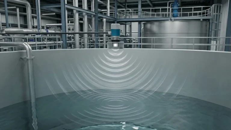
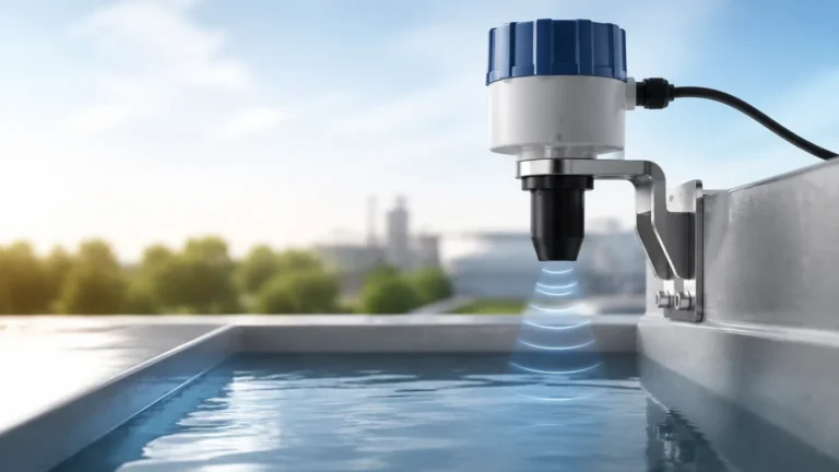
Before examining the physical assembly, it is essential to understand the Time-of-Flight (ToF) principle that dictates the sensor's construction requirements. An ultrasonic level meter operates by emitting high-frequency sound pulses (typically between 20 kHz and 200 kHz) from a transducer. These pulses travel through the air, reflect off the surface of the medium, and return to the transducer.
The distance ($D$) is calculated using the formula:
$D = (v \times t) / 2$
Where:
* $v$ is the speed of sound in the medium (usually air).
* $t$ is the elapsed time between emission and reception.
Because the speed of sound is affected by air temperature—changing by approximately 0.17% per degree Celsius—modern ultrasonic level sensor construction must include an integrated temperature probe. This allows the internal microprocessor to compensate for temperature fluctuations in real-time, ensuring accuracy across varying seasonal or process conditions.
Core Components of Ultrasonic Level Sensor Construction
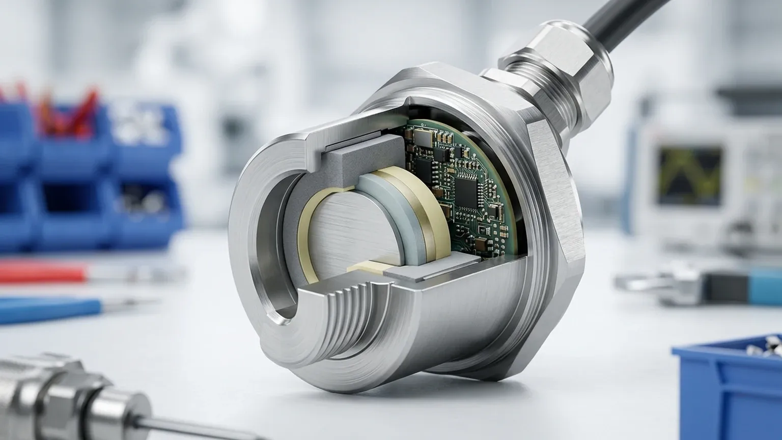
The construction of an ultrasonic level sensor is a sophisticated integration of acoustic physics, materials science, and electronic engineering. The device is generally divided into four primary modules: the transducer assembly, the electronic circuitry, the housing, and the process connection.
1. The Transducer Assembly (The Acoustic Heart)
The transducer is the most critical component. It consists of one or more piezoelectric crystals that expand and contract when subjected to an electric field (the converse piezoelectric effect). This vibration generates the ultrasonic wave. Conversely, when the reflected echo hits the crystal, it generates a small voltage that the electronics interpret as a signal.
Key elements within the transducer assembly include:
* Piezoelectric Ceramic: Usually Lead Zirconate Titanate (PZT), chosen for its high conversion efficiency.
* Matching Layer: Because there is a significant acoustic impedance mismatch between the dense ceramic and the thin air, a matching layer (often an epoxy-based resin) is applied to the face of the transducer. This layer facilitates the efficient transfer of sound energy into the air.
* Damping Material: Positioned behind the crystal to prevent internal ringing, ensuring the pulse is short and sharp for better resolution.
2. Electronic Circuitry and Signal Processing
The internal electronics are responsible for pulse generation, echo reception, and data conversion. Modern construction utilizes Surface Mount Technology (SMT) to keep the footprint small and resistant to vibration. High-end units incorporate advanced Digital Signal Processing (DSP) algorithms to filter out "false echoes" caused by internal tank obstructions like ladders or agitators.
3. Housing and Enclosures
The housing protects the sensitive electronics from the external environment. Common materials used in ultrasonic level sensor construction include:
* ABS/Polycarbonate: Used for general-purpose water and wastewater applications.
* PVDF (Polyvinylidene Fluoride): Essential for corrosive chemical environments, such as acid or alkali storage tanks.
* Stainless Steel (304 or 316L): Preferred for food and beverage applications or heavy industrial zones where mechanical impact is a risk.
4. Process Connections
This is the interface between the sensor and the vessel. Common types include threaded connections (NPT or G threads) and flanged connections. The construction must ensure a pressure-tight seal, often utilizing Viton or EPDM O-rings to prevent gas leakage from the tank into the sensor head.
Material Selection and Environmental Compatibility
Choosing the right materials during the specification phase is vital for the longevity of the instrument. The following table summarizes common construction materials and their typical applications.
| Material | Chemical Resistance | Max Temperature | Typical Application |
| :— | :— | :— | :— |
| ABS Plastic | Moderate | 60°C (140°F) | Open-air water channels, sumps |
| PVDF | Excellent (Acids/Bases) | 90°C (194°F) | Chemical storage, plating tanks |
| Polypropylene | High | 80°C (176°F) | General industrial fluids |
| Stainless Steel | High (Mechanical) | 100°C+ (Specialized) | Food processing, high-pressure zones |
Critical Installation Considerations
The physical construction of the sensor dictates how it must be installed to achieve accurate results. Engineers must account for the following factors:
The Dead Zone (Blocking Distance)
Every ultrasonic sensor has a "dead zone" immediately below the transducer face where it cannot measure. This is caused by the time required for the piezoelectric crystal to stop vibrating (ringing) after emitting a pulse. If the liquid level enters this zone, the sensor will provide an error or an incorrect reading. During construction, higher frequency sensors (e.g., 60 kHz) typically have smaller dead zones than lower frequency sensors (e.g., 20 kHz).
Beam Angle and Obstructions
The ultrasonic pulse spreads out in a cone shape. The "beam angle" is defined as the point where the energy drops to half its peak value. The construction of the transducer and the housing shape determine this angle. Installers must ensure that no internal tank structures (pipes, reinforcement bars, or pumps) intersect this beam, as they will create false echoes.
Mounting Orientation
The sensor must be mounted perfectly perpendicular to the liquid surface. If the sensor is tilted, the reflected pulse may not return to the transducer, leading to signal loss. In tanks with domed roofs, the sensor should be placed at 1/2 or 1/3 of the radius from the center to avoid the focal point of the dome's reflection.
Limitations of Ultrasonic Technology
While Ultrasonic Level Meters are versatile, their construction and physical principles impose certain limitations:
1. Vacuum Conditions: Sound cannot travel in a vacuum. Therefore, ultrasonic sensors cannot be used in vessels under a full vacuum.
2. Heavy Foam: Thick, dense foam on the surface of a liquid can absorb the ultrasonic signal, preventing an echo from returning. In these cases, a radar level meter or a magnetic level gauge may be more appropriate.
3. High Pressure/High Temperature: As pressure increases, the speed of sound changes, and high temperatures can damage the piezoelectric crystals if the housing is not specifically designed for thermal isolation.
4. Dust and Vapor: While light dust is manageable, extremely heavy dust or thick steam can scatter the sound waves, reducing the effective range of the sensor.
Maintenance and Troubleshooting
Because of their non-contact construction, ultrasonic sensors require very little maintenance. However, periodic checks are recommended:
* Transducer Face Cleaning: In applications with high humidity or splashing, condensation or buildup can occur on the transducer face. This should be wiped clean with a soft cloth and mild detergent. Do not use abrasive tools, as they can damage the matching layer.
* Cable Integrity: Ensure that the cable entry points are sealed (using proper cable glands) to prevent moisture ingress into the electronic compartment, which is a common cause of premature failure.
* Firmware Updates: Some modern digital sensors allow for firmware updates to improve signal processing algorithms for specific difficult environments.
Frequently Asked Questions (FAQ)
Q: Can ultrasonic level sensors be used for solids?
A: Yes, but with caveats. Solids like grain or plastic pellets do not reflect sound as uniformly as liquids. The sensor must usually have a higher power output and a swivel mounting bracket to align the sensor with the angle of repose of the material.
Q: How does wind affect an outdoor ultrasonic sensor?
A: Strong wind can "blow" the ultrasonic pulse away, preventing the echo from returning to the transducer. For outdoor applications in windy areas, using a stilling well or a protective shroud can help stabilize the measurement.
Q: What is the difference between an integral and a remote sensor?
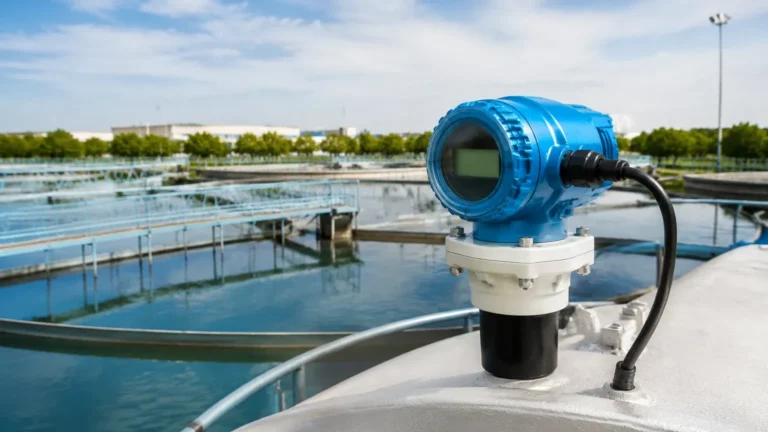
A: Integral sensors have the electronics and transducer in a single housing. Remote sensors separate the transducer (the "head") from the electronics (the "transmitter") via a cable. Remote construction is ideal for applications where the measurement point is difficult to access or subject to high vibration.
Conclusion
Understanding ultrasonic level sensor construction is the first step toward achieving a reliable and maintenance-free level measurement system. By evaluating the transducer materials, housing durability, and the specific physical constraints of the installation site, engineers can select an instrument that provides accurate data for years to come. Whether dealing with wastewater in a municipal plant or corrosive acids in a chemical facility, the right construction choices ensure that the technology meets the demands of the application.