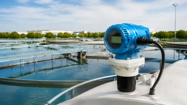
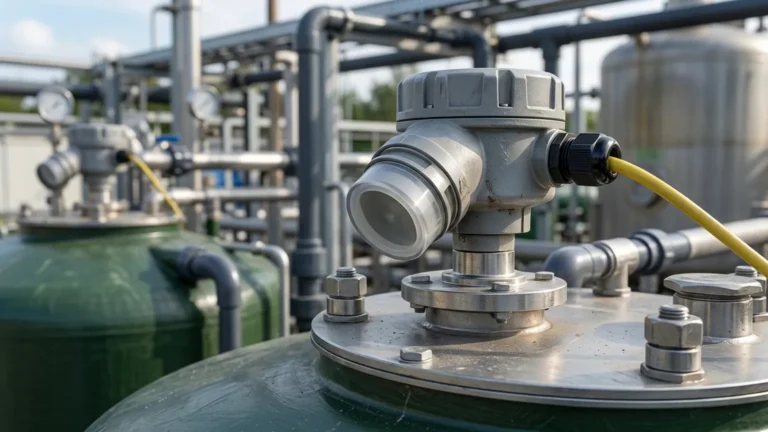
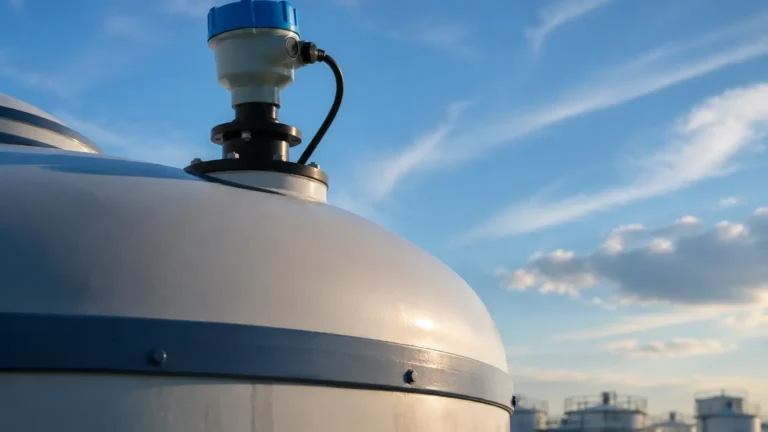
Ultrasonic Level Sensor Manual
Ultrasonic Level Sensor Manual: A Comprehensive Engineering Guide to Selection and Installation
In the realm of industrial process control, accurate level measurement is fundamental to operational efficiency, safety, and inventory management. Among the various technologies available, Ultrasonic Level Meters have emerged as a preferred non-contact solution for a wide array of liquid and solid applications. This guide serves as a practical engineering reference, detailing the principles of operation, selection criteria, and the critical information typically found within a professional ultrasonic level sensor manual to ensure successful field deployment.
Understanding Ultrasonic Level Measurement Principles
Before delving into the specifics of an ultrasonic level sensor manual, it is essential to understand the physics governing these instruments. Ultrasonic level measurement is based on the "Time-of-Flight" (ToF) principle.
The Time-of-Flight Mechanism
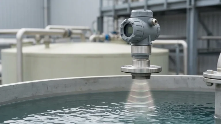
The sensor's transducer emits a series of high-frequency ultrasonic pulses (typically ranging from 20 kHz to 80 kHz). these sound waves travel through the air or vapor space above the medium, strike the surface of the material, and reflect back to the transducer. The sensor then measures the time interval between the emission of the pulse and the reception of the echo.
The distance from the sensor to the material surface is calculated using the formula:
D = (c × t) / 2
Where:
* D is the distance to the surface.
* c is the speed of sound in the medium (usually air).
* t is the measured time for the round trip.
Since the total distance of the tank (Height) is known and programmed into the device, the actual level (L) is determined by subtracting the measured distance (D) from the total height (H): L = H – D.
Temperature Compensation
The speed of sound is not constant; it varies primarily with temperature. In air, the speed of sound changes by approximately 0.17% per degree Celsius. To maintain accuracy, high-quality Ultrasonic Level Meters incorporate an integrated temperature sensor. The internal logic of the device automatically adjusts the calculation based on the ambient temperature near the transducer, ensuring reliable data despite environmental fluctuations.
Navigating the Ultrasonic Level Sensor Manual: Key Technical Specifications
An ultrasonic level sensor manual is the primary document for engineers and technicians. It contains the boundary conditions within which the sensor can operate effectively. When reviewing a manual, several technical parameters require close attention:
1. Measurement Range and Dead Zone
Every ultrasonic sensor has a minimum and maximum range. The minimum range is often referred to as the "Dead Zone" or "Blocking Distance." This is the area immediately in front of the transducer face where the sensor cannot accurately measure because the transducer is still vibrating from the pulse emission when the echo returns. Typically, for a sensor with a 10-meter range, the dead zone might be between 0.25m and 0.5m. It is critical that the maximum expected level in the tank does not enter this dead zone.
2. Beam Angle
The ultrasonic pulse does not travel in a straight line but spreads out in a conical shape. The beam angle (usually defined at the -3dB point) dictates how much space the sensor needs to avoid false reflections from tank walls, internal ladders, or agitators. A narrower beam angle (e.g., 5° to 10°) is generally preferred for tall, narrow silos or tanks with internal obstructions.
3. Output and Communication Protocols
Modern industrial sensors provide various output options. The most common is the 4-20mA analog signal, often combined with the HART protocol for digital communication. For integration into complex automation systems, manuals will specify support for Modbus RTU (RS485), Profibus, or Foundation Fieldbus.
Selection Criteria for Industrial Applications
Choosing the right instrument involves matching the process conditions with the sensor's capabilities. The following table provides a general selection framework based on typical Welk product specifications:
| Application Feature | Standard Liquid Tank | Chemical Storage | Solids/Powders | Open Channel Flow |
| :— | :— | :— | :— | :— |
| Recommended Sensor Type | Integrated Ultrasonic | PVDF/PTFE Housed | High-Power Ultrasonic | Ultrasonic with Flume Logic |
| Typical Range | 0.4m – 15m | 0.25m – 10m | 0.5m – 30m | 0.1m – 5m |
| Surface Condition | Calm/Slight Ripple | Corrosive Vapors | Dusty/Uneven | Constant Flow |
| Key Requirement | Cost-effectiveness | Chemical Resistance | High Gain/Dust Penetration | High Accuracy/Linearization |
Practical Installation and Mounting Best Practices
Correct installation is the single most important factor in the performance of an ultrasonic level meter. Even the most advanced sensor will fail if the installation violates the guidelines set forth in the ultrasonic level sensor manual.
Mounting Location
* Avoid the Center: In cylindrical tanks with domed tops, do not mount the sensor in the exact center. This can create a "parabolic" effect where the echo is focused and amplified, leading to erratic readings.
* Avoid the Fill Stream: Never mount the sensor directly above the inlet where the material enters the tank. The falling liquid or solid will interfere with the ultrasonic pulse.
* Distance from Walls: Ensure the beam does not hit the tank wall. A general rule is to keep the sensor at least 200mm away from the wall for every 1m of depth, depending on the beam angle.
Orientation and Alignment
The transducer face must be perfectly parallel to the surface of the material. If the sensor is tilted, the sound wave will reflect away from the transducer rather than back to it, resulting in a "Loss of Echo" (LOE) error. For solids applications where the material forms a cone (angle of repose), an adjustable flange or aiming kit is often required to align the sensor perpendicular to the slope of the material.
Environmental Shielding
While many Ultrasonic Level Meters are rated IP67 or IP68, they should still be protected from direct sunlight in outdoor installations. Solar heating can cause the internal temperature sensor to read higher than the actual air temperature in the tank, leading to measurement errors. A simple sunshade is a low-cost solution to maintain accuracy.

Configuration, Calibration, and Signal Tuning
Once installed, the sensor must be commissioned. The ultrasonic level sensor manual provides step-by-step instructions for setting the parameters. Most Welk sensors feature an LCD menu or can be configured via PC software.
1. Setting the Zero Point (Empty Distance): Define the distance from the transducer face to the bottom of the tank (4mA point).
2. Setting the Span (Full Distance): Define the distance representing the maximum fill level (20mA point).
3. Damping/Response Time: Adjust how quickly the sensor reacts to level changes. For tanks with turbulence, increasing the damping (e.g., to 30 seconds) helps smooth out the signal.
4. False Echo Suppression: If there is an unavoidable obstruction in the tank (like a support beam), the sensor can be programmed to "learn" the tank profile. It maps the fixed echoes and ignores them, focusing only on the moving echo from the material surface.
Limitations and Environmental Factors
Ultrasonic technology is versatile but has specific physical limitations that engineers must recognize:
* Pressure: Ultrasonic sensors are generally designed for atmospheric or near-atmospheric pressure. High pressure increases the density of the gas, while vacuum prevents sound from traveling at all.
* Heavy Foam: Thick, dense foam acts as an acoustic absorber. The ultrasonic pulse is absorbed rather than reflected, leading to signal loss. In such cases, a radar level meter or a magnetic level gauge may be more appropriate.
* Dust and Vapors: While light dust is manageable, extremely heavy dust (as found in cement silos during filling) can attenuate the signal. Similarly, heavy steam or solvent vapors can change the speed of sound significantly, requiring specialized compensation or a different technology.
Maintenance and Troubleshooting Guide
Ultrasonic sensors are low-maintenance because they have no moving parts. However, periodic checks are recommended to ensure long-term reliability.
Routine Maintenance
* Transducer Cleaning: In applications with high humidity or splashing, condensation or material buildup can occur on the transducer face. Gently wipe the face with a soft cloth and water or a mild detergent. Do not use abrasive materials or solvents that could damage the matching layer of the transducer.
* Cable Inspection: Check the cable glands and housing seals for integrity to prevent moisture ingress into the electronics compartment.
Common Troubleshooting Scenarios
* Reading stays at maximum (20mA): Check if the material has entered the dead zone. The sensor may be locking onto a reflection from the transducer face itself.
* Reading is erratic or jumps: This often indicates a weak echo. Check for foam, check the alignment of the sensor, or increase the "Gain" setting in the configuration menu.
* "Loss of Echo" (LOE) Alarm: This occurs when the sensor receives no return signal. Verify the tank is not empty beyond the programmed range, check for heavy dust/steam, and ensure the transducer face is clean.
Frequently Asked Questions (FAQ)
Q: Can I use an ultrasonic sensor in a vacuum tank?
A: No. Sound waves require a medium (gas) to travel. In a vacuum, there is no medium to carry the pulse, so the sensor will not function.
Q: How does wind affect outdoor ultrasonic level measurement?
A: Strong wind can "blow" the ultrasonic pulse away or create noise. However, for most industrial distances, this is negligible unless the sensor is mounted very high above an open reservoir.
Q: What is the difference between an integrated and a remote ultrasonic meter?
A: An integrated meter has the transducer and electronics in one housing. A remote meter has a separate transducer connected via cable to a wall-mounted controller. Remote versions are useful for hazardous areas or when the display needs to be at eye level while the sensor is at the top of a tall tank.
Q: Can ultrasonic sensors measure the level of solids?
A: Yes, but with caveats. Solids reflect sound less efficiently than liquids and often have uneven surfaces. You must select a sensor with sufficient power and often use an aiming flange to get a reliable echo.
By following the technical guidelines outlined in the ultrasonic level sensor manual and understanding the environmental constraints of the application, engineers can implement robust and accurate level control systems. For specific model data and application support, always refer to the manufacturer's provided documentation to ensure compliance with local safety and operational standards.