Ultrasonic Levels
Ultrasonic Levels
In the landscape of industrial automation and process control, the ability to monitor liquid and solid volumes accurately is fundamental to operational efficiency and safety. Among the various technologies available, non-contact measurement via ultrasonic waves has emerged as one of the most versatile and cost-effective solutions. This guide provides a technical overview of how to evaluate, install, and maintain Ultrasonic Level Meters to ensure reliable performance in diverse industrial environments.
Understanding the Principle of Ultrasonic Level Measurement
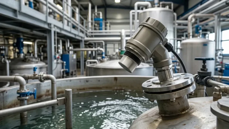
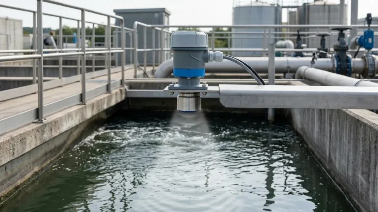
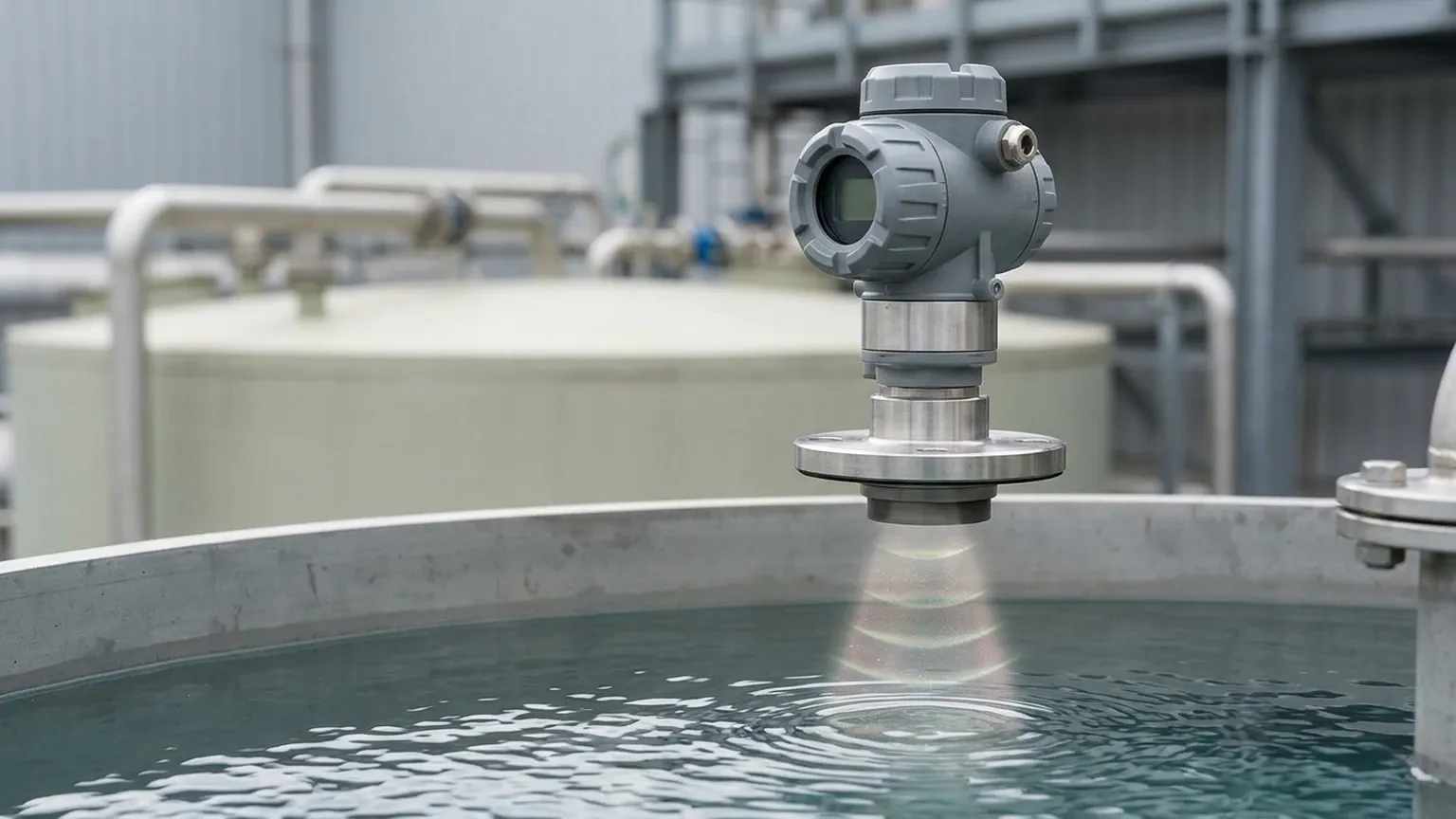
Ultrasonic level measurement is based on the "Time of Flight" (ToF) principle. The instrument, typically mounted at the top of a vessel or above a channel, contains a transducer that emits high-frequency sound pulses. These pulses travel through the air at the speed of sound, strike the surface of the medium (liquid or solid), and reflect back to the sensor.
The Calculation of Distance
The electronics within the meter measure the time interval between the emission of the pulse and the reception of the echo. The distance from the sensor to the material surface is calculated using the following formula:
D = (c × t) / 2
Where:
* D is the distance to the surface.
* c is the speed of sound in the medium (typically air, approximately 344 m/s at 20°C).
* t is the elapsed time (Time of Flight).
Because the pulse must travel to the surface and back, the total distance is divided by two. By knowing the total height of the tank (the "empty" distance), the instrument subtracts the measured distance from the total height to determine the actual level of the product.
Frequency and Resolution
Most industrial ultrasonic levels operate at frequencies ranging from 20 kHz to 70 kHz. Higher frequencies generally offer better resolution and are more effective at penetrating light vapors, but they have a shorter effective range. Lower frequencies are used for longer distances (up to 30 or 40 meters) because they suffer less attenuation as they travel through the air.
Key Components of Ultrasonic Level Meters
A professional-grade ultrasonic system consists of several critical components designed to withstand industrial rigors:
1. The Transducer: Often made from piezoelectric crystals housed in chemically resistant materials like PVDF or Polypropylene. This component converts electrical energy into mechanical sound waves and vice versa.
2. Signal Processing Electronics: Advanced algorithms are used to filter out "noise" or false echoes caused by internal tank structures, agitators, or turbulence. This is often referred to as "echo mapping" or "false echo suppression."
3. Temperature Sensor: Since the speed of sound varies with air temperature (changing by approximately 0.17% per degree Celsius), an integrated thermistor compensates for these fluctuations to maintain accuracy.
4. Housing: Usually rated IP66, IP67, or IP68 to protect against moisture and dust ingress.
Evaluating Ultrasonic Levels for Specific Applications
While ultrasonic technology is robust, its success depends heavily on the physical properties of the application. Engineers must consider the state of the medium and the environment above it.
Liquid Level Monitoring
Ultrasonic sensors excel in measuring water, wastewater, oils, and many chemicals. They are preferred in water treatment plants for monitoring open channels, flumes, and weirs because they do not come into contact with potentially corrosive or fouling liquids.
Solid Level Monitoring
Measuring solids (pellets, grains, powders) is more challenging. Unlike liquids, solids do not always form a flat surface; they can form cones or depressions. Furthermore, the granular nature of solids tends to absorb sound waves rather than reflecting them cleanly. In these cases, higher-powered transducers and specialized aiming flanges are often required to capture a reliable return signal.
Selection Criteria and Technical Specifications
Choosing the right instrument requires a detailed understanding of the process parameters. The following table outlines the typical selection criteria for standard industrial projects.
Table 1: Ultrasonic Level Meter Selection Matrix
| Feature | Standard Liquid Application | Challenging/Solid Application |
| :— | :— | :— |
| Measurement Range | 0.3m to 15m | 0.5m to 30m+ |
| Beam Angle | 5° to 10° (Narrow is better) | 10° to 12° (Wide for uneven surfaces) |
| Accuracy | ±0.25% to ±0.5% of range | ±0.5% to ±1% of range |
| Output Signal | 4-20mA, HART, RS485 | 4-20mA, Modbus, Profibus |
| Process Temp. | -40°C to +70°C | -40°C to +90°C |
| Process Pressure | Atmospheric (±0.3 bar) | Atmospheric (±0.3 bar) |
| Housing Material | ABS / Cast Aluminum | Stainless Steel / Epoxy Coated |
The "Dead Zone" (Blocking Distance)
Every ultrasonic sensor has a "dead zone" immediately in front of the transducer face where it cannot measure. This is caused by the time required for the transducer to stop vibrating after emitting a pulse before it can begin listening for the echo. Typically, this ranges from 0.2m to 0.8m depending on the frequency. It is vital to mount the sensor high enough so that the maximum liquid level never enters this zone.
Installation Best Practices for Maximum Accuracy
Proper installation is the single most important factor in the reliability of ultrasonic levels. Even the most advanced meter will fail if the physical mounting ignores the laws of physics governing sound waves.
1. Positioning and Orientation
* Perpendicularity: The transducer face must be perfectly parallel to the liquid surface. A tilt of even a few degrees can cause the reflected signal to bounce away from the sensor rather than back to it.
* Avoid the Center: In tanks with domed tops, do not mount the sensor in the exact center. Domed roofs can act as a parabolic dish, concentrating multiple reflections and creating false signals. The ideal position is usually 1/2 to 1/3 of the radius from the tank wall.
* Stay Away from the Wall: Do not mount the sensor too close to the tank wall. Sound waves spread out in a cone; if the cone hits a rough wall or a weld seam, it will create interference. A general rule is to keep the sensor at least 20cm from the wall for every 1m of depth.
2. Obstruction Management
Internal structures such as ladders, heating coils, or fill pipes can reflect sound waves. While modern software can "map out" these fixed obstructions, it is best to avoid them entirely during the design phase. Ensure the "signal cone" (based on the beam angle) is clear of any physical objects.
3. Avoiding the Fill Stream
Never mount an ultrasonic sensor directly over the inlet pipe. The turbulence and falling liquid will scatter the sound waves and create significant noise, leading to erratic readings or a total loss of signal.
Limitations and Environmental Interference
While ultrasonic technology is highly capable, it is not a universal solution. Certain environmental factors can attenuate or distort the sound signal.
* Foam: Heavy, thick foam on the surface of a liquid is a primary enemy of ultrasonic measurement. Foam acts as an acoustic insulator, absorbing the sound pulse rather than reflecting it. If foam is present, a radar level meter or a hydrostatic transmitter may be a better choice.
* Vacuum: Sound requires a medium (air or gas) to travel. Therefore, ultrasonic meters cannot function in a vacuum.
* Heavy Dust and Vapors: While light dust is manageable, extremely dense dust (common in grain silos during filling) or heavy chemical vapors can change the density of the air, affecting the speed of sound and causing measurement errors.
* High Pressure: Ultrasonic transducers are generally designed for atmospheric pressure. High-pressure environments change the air density significantly, which can dampen the transducer's vibration and alter the sound speed beyond the capacity of standard compensation algorithms.
Maintenance and Troubleshooting
Ultrasonic level meters are largely maintenance-free because they have no moving parts and do not touch the medium. However, occasional checks are recommended:
* Transducer Cleaning: In humid or dusty environments, condensation or buildup can occur on the transducer face. A gentle wipe with a soft cloth and mild detergent is usually sufficient.
* Signal Strength Monitoring: Most modern meters provide a "Gain" or "Echo Strength" value. If this value drops over time, it may indicate a failing transducer or an increase in environmental interference (like steam or foam).
* Diagnostic Codes: If the meter displays a "Loss of Echo" (LOE) error, check for surface turbulence, foam, or whether the level has risen into the dead zone.
Frequently Asked Questions (FAQs)
Q: Can ultrasonic levels be used on sulfuric acid or other corrosive chemicals?
A: Yes, provided the transducer is made from a compatible material like PVDF. Since the measurement is non-contact, the sensor is protected from the bulk of the liquid, but it must still withstand the corrosive vapors.
Q: How does wind affect an outdoor ultrasonic installation?
A: Strong winds can "blow" the sound pulse away, especially over long distances (e.g., measuring a river level from a high bridge). In these cases, using a stilling well or a higher-power transducer can help stabilize the reading.
Q: What is the difference between an ultrasonic level transmitter and a switch?
A: A transmitter provides a continuous measurement (e.g., 0-100%), whereas a switch only triggers a signal when the liquid reaches a specific point (e.g., high-level alarm).
Q: Can I use an ultrasonic meter in a pressurized tank?
A: Generally, no. Most ultrasonic sensors are rated for near-atmospheric pressure. For pressurized vessels, radar technology is typically the preferred non-contact alternative.
Conclusion
Ultrasonic Level Meters represent a mature, reliable, and cost-effective technology for a vast array of industrial level-sensing needs. By understanding the underlying physics of sound travel and adhering to strict installation guidelines regarding beam angles and dead zones, engineers can implement systems that provide years of maintenance-free service. When selecting a device, always prioritize the chemical compatibility of the transducer and the specific environmental conditions of the vessel to ensure the highest level of accuracy and safety in your process automation.