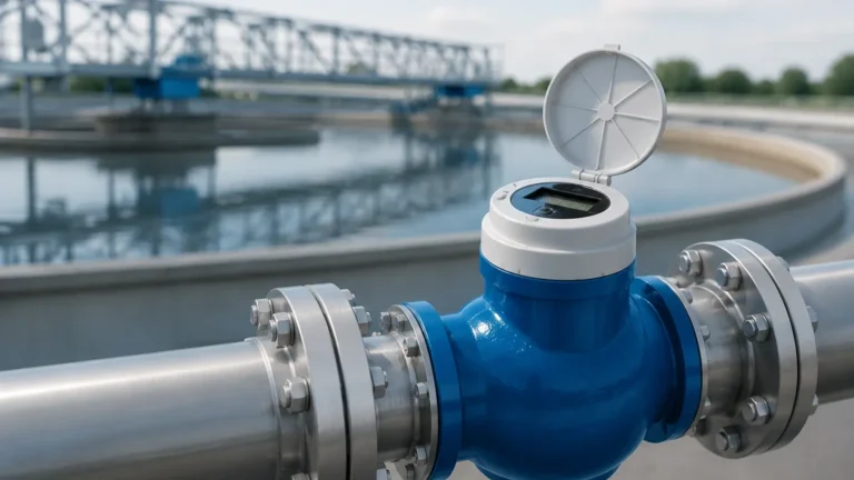
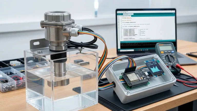
Ultrasonic Meter K Factor
Understanding the Ultrasonic Meter K Factor in Industrial Level and Flow Measurement
In modern industrial process control, precision is the cornerstone of operational efficiency. Among the various technologies available for monitoring liquids and solids, ultrasonic measurement stands out for its non-contact nature and versatility. However, achieving high-accuracy results—particularly when converting level data into flow rates—requires a deep understanding of specific calibration parameters. One of the most critical variables in this process is the ultrasonic meter k factor.
For engineers and plant managers utilizing Ultrasonic Level Meters, the K-factor is not merely a number but a fundamental coefficient that bridges the gap between raw distance measurement and actionable volume or flow data. This guide explores the principles of ultrasonic technology, the technical definition of the K-factor, and how to optimize these instruments for industrial applications.
Measurement Principles of Ultrasonic Technology
Before delving into the complexities of the K-factor, it is essential to understand how ultrasonic instruments function. Welk, a professional manufacturer of industrial level measurement instruments, designs these sensors to operate on the "Time-of-Flight" (ToF) principle.
The Time-of-Flight Principle
An ultrasonic transducer emits high-frequency sound pulses (typically between 20 kHz and 200 kHz). These waves travel through the air, strike the surface of the medium (liquid or solid), and reflect back to the sensor. The instrument measures the time interval between the emission of the pulse and the reception of the echo.
The distance ($D$) from the sensor to the material surface is calculated using the formula:
$$D = \frac{c \times t}{2}$$
Where:
* $c$ is the speed of sound in the medium (usually air).
* $t$ is the total transit time.
Since the mounting height ($H$) of the sensor is known, the level ($L$) of the material is determined by subtracting the measured distance from the total height ($L = H – D$).
Transitioning from Level to Flow
In many B2B applications, such as water treatment or chemical processing, ultrasonic sensors are installed over primary devices like flumes or weirs to measure open-channel flow. This is where the ultrasonic meter k factor becomes indispensable. The sensor measures the "head" (the height of the liquid above a reference point), and the internal software applies a mathematical formula to convert that height into a volumetric flow rate.
What is the Ultrasonic Meter K Factor?
In the context of ultrasonic instrumentation, the term "K-factor" can refer to two distinct but related concepts depending on the specific application: flow measurement or sensor calibration.
1. The Discharge Coefficient (Flow K-Factor)
When measuring flow in an open channel, the relationship between the head ($h$) and the flow rate ($Q$) is generally expressed by the equation:
$$Q = K \times h^n$$
In this equation, $K$ is the K-factor. It is a constant that accounts for the specific geometry of the flume or weir (e.g., a Parshall flume, V-notch weir, or rectangular weir). The exponent $n$ varies based on the shape of the primary device. Without an accurate K-factor programmed into the meter, the flow readings will be fundamentally flawed, leading to errors in billing, chemical dosing, or regulatory reporting.
2. The Pulse-to-Volume Ratio
In some specialized ultrasonic flow meters (specifically inline transit-time meters), the K-factor represents the number of pulses produced per unit of volume (e.g., pulses per liter). This ensures that the digital output of the meter aligns perfectly with the physical volume passing through the pipe.
3. Calibration Correction Factor
In level-only applications, a K-factor may be used as a scaling multiplier to correct for environmental variables or specific tank geometries that might cause consistent linear deviations in measurement.
Practical Selection: Choosing the Right Ultrasonic Instrument
Selecting the appropriate hardware is the first step in ensuring a stable K-factor and reliable measurements. Welk offers a range of solutions tailored to different industrial environments.
Selection Table: Ultrasonic Level Meter Configurations
| Feature | Integrated Type | Remote/Split Type | High-Precision Series |
| :— | :— | :— | :— |
| Best Use Case | Standard tanks, compact spaces | Hazardous areas, sumps | Open channel flow, custody transfer |
| Measurement Range | 0.4m to 15m | 0.4m to 30m | 0.2m to 10m |
| Output Options | 4-20mA, RS485 | 4-20mA, Relay, Modbus | 4-20mA, HART, Modbus |
| K-Factor Support | Basic scaling | Advanced flow curves | Pre-programmed flume/weir library |
| Protection Class | IP65/IP67 | IP68 (Sensor) / IP65 (Host) | IP67 |
How to Determine and Program the K-Factor
For engineers, the ultrasonic meter k factor is typically derived from the manufacturer's documentation for the primary flow device.
1. Identify the Primary Device: Determine if you are using a Parshall flume, a Palmer-Bowlus flume, or a specific weir type.
2. Consult Standard Tables: Reference ISO or ASTM standards that provide the $K$ and $n$ values for the specific dimensions of your flume.
3. Manual Calculation: If the flume is custom-built, the K-factor must be determined through empirical testing or hydraulic modeling.
4. Input into the Transmitter: Most modern Ultrasonic Level Meters allow users to select the flume type from a menu, which automatically sets the K-factor. For custom setups, the "Fixed K-Factor" mode is used to manually enter the coefficient.
Installation Considerations for Accuracy
The accuracy of the K-factor is only as good as the physical installation of the sensor. Poor placement can lead to signal turbulence, which the K-factor cannot correct.
* Dead Zone Management: Every ultrasonic sensor has a "dead zone" (typically 0.2m to 0.5m) near the transducer face where measurements are impossible. Ensure the maximum liquid level never enters this zone.
* Perpendicular Alignment: The transducer face must be perfectly parallel to the liquid surface. A tilt of even a few degrees can cause the signal to bounce away, leading to "lost echo" errors.
* Avoid Obstructions: Do not mount the sensor near ladders, pipes, or agitators. These create false echoes that interfere with the primary measurement.
* Positioning in Flumes: For open channel flow, the sensor must be placed at a specific distance upstream from the throat of the flume (usually 2/3 of the way back in the converging section) to ensure a stable head measurement.
Limitations and Environmental Factors
While ultrasonic meters are robust, certain factors can influence the speed of sound, effectively shifting the required calibration or K-factor performance.
1. Temperature Variations: The speed of sound changes by approximately 0.17% per degree Celsius. Welk instruments include built-in temperature compensation to adjust the calculation in real-time.
2. Vapor and Heavy Dust: High concentrations of steam or heavy dust can attenuate the ultrasonic signal. In such cases, high-power transducers or radar level meters may be more appropriate.
3. Surface Foam: Thick foam absorbs ultrasonic pulses rather than reflecting them. If foam is present, the meter may report a "lost signal" or provide erratic readings.
4. Pressure: Ultrasonic sensors are generally designed for atmospheric pressure. Significant pressure changes alter the density of the air, which impacts the speed of sound and measurement accuracy.
Maintenance and Calibration Checklist
To ensure the ultrasonic meter k factor remains accurate over time, a regular maintenance schedule is recommended:
* Transducer Cleaning: Periodically wipe the transducer face to remove moisture or dust buildup.
* Zero-Point Verification: Empty the channel or tank and verify that the meter reads zero. If not, recalibrate the empty distance.
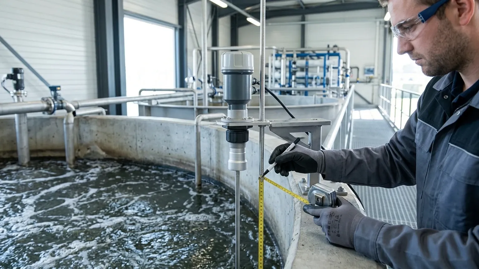
* Secondary Verification: Use a manual dipstick or staff gauge to compare the physical level with the meter's reading. If a discrepancy exists, check if the K-factor or the speed-of-sound setting needs adjustment.
* Firmware Updates: Ensure the transmitter software is updated to the latest version to benefit from improved signal processing algorithms.
Frequently Asked Questions (FAQs)
Q: Can I use the same K-factor for different sizes of the same flume type?
A: No. The K-factor is specific to the dimensions of the primary device. For example, a 3-inch Parshall flume has a different K-factor than a 6-inch Parshall flume.
Q: Why is my flow reading fluctuating even though the level is steady?
A: This is often caused by surface turbulence or electrical interference. Increasing the "damping" or "averaging" time in the meter settings can smooth out these fluctuations without changing the K-factor.
Q: Does the K-factor change if the liquid density changes?
A: No. Ultrasonic level measurement is independent of liquid density, viscosity, or conductivity, provided the surface reflects the sound wave. This is a major advantage over hydrostatic pressure sensors.
Q: How do I handle a custom tank shape that isn't in the meter's library?
A: Most Welk Ultrasonic Level Meters support a "Linearization Table" or "Multi-point Calibration." You can input a series of level-to-volume points, and the meter will interpolate the values, effectively creating a custom K-factor curve for your specific tank.
Conclusion
The ultrasonic meter k factor is a vital link in the chain of industrial process automation. By correctly identifying the coefficient required for your specific flume, weir, or vessel, and ensuring the instrument is installed according to engineering best practices, you can achieve highly accurate and repeatable measurements. Whether you are managing wastewater discharge or monitoring chemical inventory, understanding the synergy between ultrasonic physics and calibration constants is essential for operational success.