Ultrasonic Level Sensor Esp32
Ultrasonic Level Sensor ESP32: A Practical Guide for Industrial IoT Integration
In the era of Industrial IoT (IIoT), the demand for remote, real-time monitoring of liquid levels has seen a significant surge. Engineering teams are increasingly looking for ways to bridge the gap between traditional industrial instrumentation and modern cloud-based data architectures. One of the most versatile approaches involves integrating high-performance sensors with powerful microcontrollers. The combination of an ultrasonic level sensor esp32 platform offers a robust solution for data acquisition, edge processing, and wireless transmission in water treatment, chemical storage, and logistics applications.
While hobbyist modules are common in the maker community, industrial-grade applications require a deeper understanding of measurement physics, signal conditioning, and hardware reliability. This guide explores the principles of ultrasonic technology, the technical nuances of ESP32 integration, and the criteria for selecting professional-grade Ultrasonic Level Meters for scalable industrial projects.
Understanding Ultrasonic Level Measurement Principles
Before implementing an ultrasonic level sensor esp32 system, it is essential to understand how the underlying technology functions. Ultrasonic level measurement is a non-contact method that relies on the properties of sound waves.
The Time-of-Flight (ToF) Principle
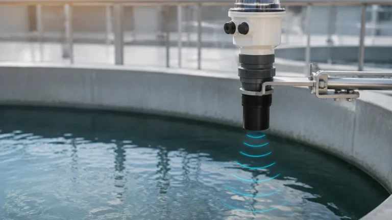
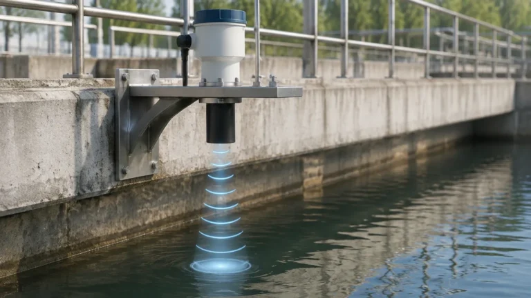
An ultrasonic transducer emits high-frequency sound pulses (typically between 20 kHz and 200 kHz). These pulses travel through the air, strike the surface of the medium (liquid or solid), and reflect back toward the sensor. The sensor’s electronics measure the time interval between the emission of the pulse and the reception of the echo.
The distance is calculated using the formula:
Distance = (Speed of Sound × Time) / 2
Since the speed of sound in air is approximately 343 meters per second (at 20°C), the system can determine the distance to the surface with high precision. By subtracting this distance from the total height of the vessel, the actual level of the material is determined.
The Role of Temperature and Medium
The speed of sound is not constant; it fluctuates based on the temperature of the air through which it travels. For every 1°C change in temperature, the speed of sound changes by approximately 0.6 m/s. Therefore, professional ultrasonic level meters incorporate internal temperature sensors to provide automatic compensation, ensuring accuracy across varying environmental conditions.
Integrating Ultrasonic Level Sensors with ESP32 for IIoT
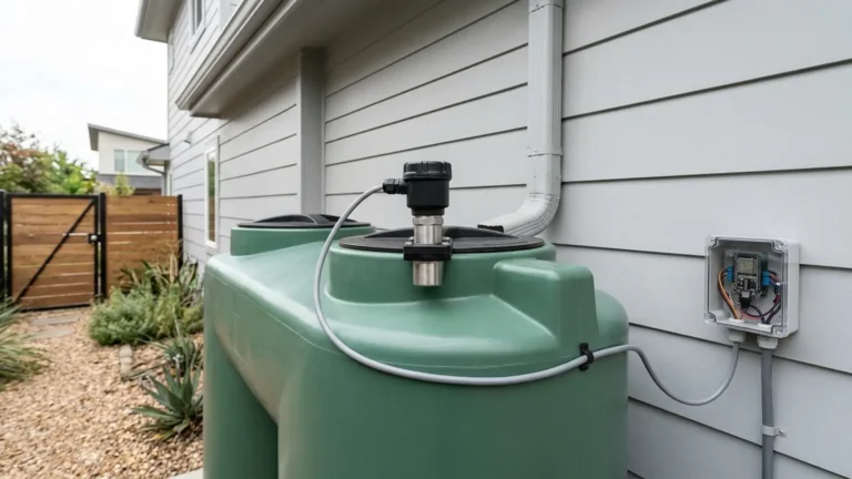
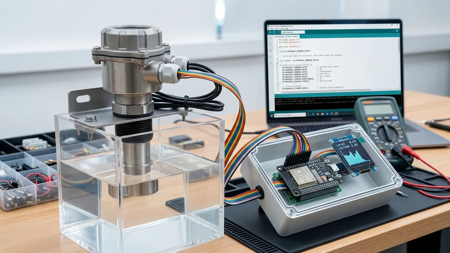
The ESP32 has become a preferred microcontroller for industrial prototyping and edge gateway applications due to its dual-core processor, integrated Wi-Fi and Bluetooth, and extensive GPIO (General Purpose Input/Output) capabilities. When building an ultrasonic level sensor esp32 system, the microcontroller acts as the bridge between the raw sensor data and the end-user interface.
Hardware Interface Options
Depending on the specific sensor selected, the ESP32 can interface via several protocols:
1. Pulse Width (TTL): Common in entry-level sensors where the "Echo" pin remains high for a duration proportional to the distance.
2. RS485/Modbus RTU: The standard for industrial environments. Using a TTL-to-RS485 converter, the ESP32 can communicate with professional sensors over long distances (up to 1,200 meters) with high noise immunity.
3. 4-20mA Analog: Requires an Analog-to-Digital Converter (ADC) or a precision resistor to convert the current loop into a voltage readable by the ESP32’s 3.3V pins.
Data Processing and Connectivity
The ESP32 allows for on-device data filtering. Since ultrasonic signals can occasionally suffer from "noise" or false echoes, developers can implement moving average filters or median filters directly on the ESP32 to ensure the transmitted data is stable. Once processed, the data can be sent via MQTT or HTTP to a centralized SCADA system or a cloud dashboard.
Key Selection Criteria for Industrial Level Sensing
Choosing the right hardware involves balancing cost, environment, and required precision. The following table compares common sensor characteristics encountered when designing an ultrasonic level sensor esp32 project versus deploying integrated industrial meters.
Comparison Table: Sensor Selection Attributes
| Feature | Entry-Level Modules (e.g., HC-SR04/JSN-SR04) | Industrial Ultrasonic Transmitters |
| :— | :— | :— |
| Measurement Range | 0.02m to 4m | 0.3m to 30m+ |
| Ingress Protection | IP20 to IP65 (limited) | IP67 / IP68 (Fully Waterproof) |
| Accuracy | ±3mm to ±10mm | ±0.2% to ±0.5% of range |
| Operating Temp | 0°C to 60°C | -40°C to +80°C |
| Output Options | TTL Pulse | 4-20mA, RS485, HART |
| Chemical Resistance | Low (Plastic) | High (PVDF, PTFE, PP) |
| Dead Zone | 2cm to 20cm | 20cm to 50cm (model dependent) |
For B2B applications where downtime is costly, opting for professional Ultrasonic Level Meters ensures long-term reliability and compliance with industrial safety standards.
Installation Best Practices and Geometric Considerations
The physical installation of the sensor is as critical as the electronic configuration. Incorrect mounting is the leading cause of signal failure in ultrasonic systems.
1. Avoiding the Dead Zone (Blocking Distance)
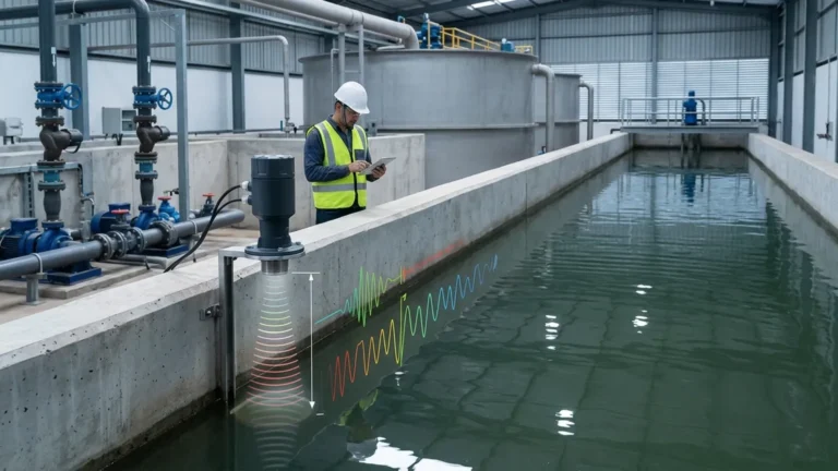
Every ultrasonic sensor has a "dead zone" immediately in front of the transducer face where it cannot accurately process echoes. If the liquid level rises into this zone, the sensor may report erratic values or a full-scale error. Always mount the sensor high enough so that the maximum expected liquid level remains below the dead zone boundary.
2. Beam Angle and Obstructions
Ultrasonic waves spread out in a cone shape (typically 5° to 15°). If this beam hits a tank wall, a ladder, or a cooling pipe, it will create a false echo.
* Rule of Thumb: Install the sensor at a distance from the wall equal to at least 10% of the total tank height.
* Alignment: Ensure the transducer face is perfectly parallel to the liquid surface to maximize the return signal strength.
3. Turbulence and Foam
Agitators or heavy inflow can create surface turbulence or foam. Foam is particularly challenging because it absorbs the ultrasonic pulse rather than reflecting it. In such cases, a stilling well (a vertical pipe) can be used to provide a calm surface for the sensor to measure, though this requires careful venting to ensure the level inside the pipe matches the level outside.
Environmental Limitations and Signal Interference
While ultrasonic sensors are highly effective, they are not universal solutions. Engineers must be aware of specific limitations:
* Vacuum Conditions: Sound requires a medium to travel. Ultrasonic sensors cannot function in a vacuum.
* High Pressure/Vapor: High-pressure environments or heavy steam can change the air density, significantly altering the speed of sound and causing measurement errors.
* Acoustic Noise: Heavy machinery operating at similar frequencies can occasionally interfere with the sensor’s ability to distinguish its own echo.
* Dust and Condensation: While industrial sensors are sealed, heavy dust accumulation or thick condensation on the transducer face can dampen the signal. Many professional Welk sensors feature self-cleaning properties or high-energy pulses to penetrate light buildup.
Maintenance and Troubleshooting for ESP32-Based Systems
When deploying an ultrasonic level sensor esp32 solution in the field, maintenance protocols should be established to ensure data integrity.
Power Stability
The ESP32 is sensitive to power fluctuations, especially when the Wi-Fi radio is active. In industrial settings, use a high-quality DC-DC buck converter to step down 24V plant power to a stable 3.3V or 5V for the microcontroller and sensor. Adding decoupling capacitors near the ESP32 power pins can prevent resets caused by voltage dips.
Troubleshooting Common Issues
1. Constant "Max Distance" Reading: This usually indicates the sensor is not receiving an echo. Check for misalignment or whether the surface is too agitated or foamy.
2. Erratic Jumping Values: This is often caused by electrical noise or the beam hitting an internal obstruction. Implement software filtering on the ESP32 and check the beam path.
3. Zero Reading: The liquid may have entered the dead zone. Lower the liquid level or raise the sensor mount.
Frequently Asked Questions (FAQ)
Q: Can I use an ESP32 to monitor chemical tanks?
A: Yes, provided you use an industrial-grade ultrasonic sensor with a chemically resistant housing (like PVDF) and interface it with the ESP32 via RS485 or a 4-20mA converter. The ESP32 itself should be housed in an appropriately rated NEMA or IP-rated enclosure.
Q: How do I handle distance measurements over 10 meters?
A: For distances beyond 5-10 meters, standard hobbyist sensors are insufficient. You should utilize high-power industrial Ultrasonic Level Meters designed for long-range detection, which provide the necessary acoustic power to receive echoes from 20 or 30 meters.
Q: Is Wi-Fi reliable enough for industrial level monitoring?
A: Wi-Fi is suitable for monitoring and data logging. However, for critical control loops (e.g., preventing a tank overflow that could cause a hazard), a wired connection like 4-20mA or Modbus is recommended as the primary fail-safe, with the ESP32/Wi-Fi serving as a secondary monitoring layer.
Q: Does the ESP32 need a specific library for ultrasonic sensors?
A: For simple TTL sensors, libraries like `NewPing` are popular. For industrial Modbus sensors, you will need a ModbusMaster library and a hardware Serial port on the ESP32 to handle the communication protocol.
By combining the computational flexibility of the ESP32 with the precision of professional ultrasonic transducers, organizations can develop cost-effective, scalable, and highly accurate level monitoring networks. Whether building a custom gateway or deploying a turnkey industrial solution, understanding the acoustic environment and hardware limitations is the key to engineering success.