Horn Antenna Radar Level Transmitter
Horn Antenna Radar Level Transmitter: Engineering Principles and Application Guide
In the field of industrial process control, accurate level measurement is critical for inventory management, process safety, and operational efficiency. Among the various technologies available, non-contacting radar has emerged as a gold standard for challenging environments. Specifically, the horn antenna radar level transmitter represents a versatile and robust solution for measuring liquids, slurries, and some solids.
This guide examines the underlying physics of radar measurement, the specific advantages of horn antenna designs, and the engineering considerations required for successful deployment in industrial settings. For those evaluating specific hardware, Radar Level Meters provide the necessary precision for complex chemical and petrochemical applications.
1. Measurement Principles of Radar Level Meters
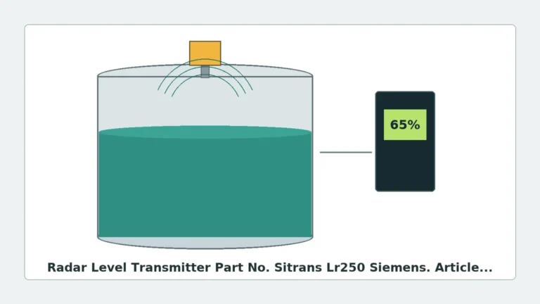
Radar level measurement operates on the principle of Time of Flight (ToF). The instrument, mounted at the top of a vessel, emits high-frequency electromagnetic waves (microwaves) toward the product surface. These waves travel at the speed of light ($c \approx 3 \times 10^8$ m/s).
The Time-of-Flight Equation
The distance ($D$) from the reference point of the sensor to the product surface is calculated using the formula:
$$D = \frac{c \times t}{2}$$
Where:
* $c$ is the speed of light.
* $t$ is the measured time delay between the emission of the pulse and the reception of the echo.
Modern industrial Radar Level Meters typically utilize one of two modulation techniques:
1. Pulse Radar: The transmitter sends out short microwave pulses and measures the time it takes for the pulse to return. This method is energy-efficient and suitable for long-range measurements.
2. FMCW (Frequency Modulated Continuous Wave): The transmitter emits a continuous signal with a constantly changing frequency. The difference in frequency between the transmitted and received signal is proportional to the distance. FMCW is generally preferred for its higher accuracy and better signal-to-noise ratio in turbulent conditions.
The Role of the Horn Antenna
The antenna is the interface between the electronic circuitry of the transmitter and the process environment. A horn antenna radar level transmitter uses a flared metal waveguide to direct the microwave energy. The primary functions of the horn are to:
* Impedance Matching: Transition the electromagnetic wave from the waveguide to the free space of the tank with minimal reflection.
* Focusing: Concentrate the energy into a specific beam angle. A larger horn diameter results in a narrower beam, which reduces the likelihood of interference from tank internals like ladders, agitators, or heating coils.
2. Technical Specifications and Selection Criteria
Selecting the correct horn antenna configuration requires an understanding of the process medium and the physical constraints of the vessel.
Frequency Bands
Industrial radar transmitters typically operate in the C-band (~6 GHz), K-band (~26 GHz), or W-band (~80 GHz).
* 26 GHz (K-band): This is the most common frequency for horn antenna designs. It offers a good balance between beam focus and the ability to penetrate moderate levels of steam or dust.
* 80 GHz (W-band): While often associated with lens antennas, 80 GHz technology allows for extremely small horn diameters with very narrow beam angles (as low as 3°), making it ideal for tall, narrow silos or tanks with many internal obstructions.
Dielectric Constant ($ε_r$)
The reflectivity of the medium is determined by its dielectric constant. Materials with high $ε_r$ (e.g., water, $ε_r \approx 80$) reflect radar waves strongly. Materials with low $ε_r$ (e.g., hydrocarbons, $ε_r < 2$) allow waves to penetrate, resulting in a weaker return signal.
| Medium Type | Dielectric Constant ($ε_r$) | Reflectivity | Recommended Antenna |
| :— | :— | :— | :— |
| Aqueous Solutions | > 20 | High | Standard Horn |
| Oils / Hydrocarbons | 1.9 – 4.0 | Medium | Large Horn / FMCW |
| Liquefied Gases | 1.1 – 1.9 | Very Low | Still-pipe or High-Gain Horn |
| Solids / Powders | 1.5 – 10 | Variable | Large Horn with Aiming Flange |
Pressure and Temperature
Horn antennas are typically constructed from 316L stainless steel, but the process seal (the "window" through which the radar passes) is often PTFE, PEEK, or Ceramics. Engineering teams must ensure these materials are compatible with the process chemistry and the maximum operating pressure/temperature.
3. Installation Guidelines and Constraints
Proper installation of a horn antenna radar level transmitter is vital to ensure signal integrity. Even the most advanced signal processing software cannot compensate for a poorly positioned sensor.
Nozzle Considerations
The horn should ideally extend past the bottom of the mounting nozzle. If the horn is recessed within the nozzle, the microwave energy will reflect off the nozzle walls, creating a "ringing" effect or a large dead zone at the top of the tank.
* Nozzle Diameter: Must be larger than the horn diameter.
* Nozzle Height: Should be kept as short as possible. If a long nozzle is unavoidable, an antenna extension or a specific "nozzle-resistant" horn design may be required.
Positioning and Clearances
1. Avoid the Center: Do not mount the transmitter in the exact center of a domed-roof tank, as this can concentrate multiple reflections (parabolic effect) and cause signal loss.
2. Wall Distance: Maintain a minimum distance from the tank wall, typically 1/10th of the tank height or at least 200 mm, to prevent side-lobe interference.
3. Obstructions: Ensure the "signal beam" (defined by the beam angle) is clear of agitator blades, ladders, and fill streams. If an obstruction is unavoidable, many Welk radar units feature "False Echo Suppression" to digitally ignore these static reflections.
Orientation
The antenna must be mounted perpendicular to the product surface. For solids measurement, where the material forms a cone, an adjustable aiming flange is often used to tilt the horn toward the angle of repose to maximize the reflected signal.
4. Application Risks and Mitigation
While highly reliable, certain process conditions can challenge a horn antenna radar level transmitter.
Foam and Turbulence
Heavy, dense foam can absorb radar signals, leading to signal loss. In such cases, a lower frequency (C-band) or a guided wave radar might be more effective. For surface turbulence caused by agitators, using a transmitter with high-speed FMCW processing can help average out the fluctuations.
Condensation and Buildup
In applications involving high humidity or sticky media, condensation can form on the antenna. While small droplets usually do not affect 26 GHz signals, heavy buildup can attenuate the signal.
* Mitigation: Use a horn antenna with a PTFE "dust cover" or a purging connection. A purging connection allows compressed air or nitrogen to be blown through the horn to keep it clean.
Heavy Steam and Vapor
High-pressure steam can change the propagation speed of microwaves slightly, leading to a small measurement error (usually < 1%). In extreme cases, the steam density may attenuate the signal. Selecting a higher-gain horn antenna helps overcome this attenuation.

5. Comparison: Horn vs. Other Antenna Types
| Feature | Horn Antenna | Rod Antenna | Lens Antenna |
| :— | :— | :— | :— |
| Beam Angle | Narrow (8° – 20°) | Wide (> 25°) | Very Narrow (3° – 6°) |
| Chemical Resistance | High (with PTFE seal) | Excellent (All-plastic) | High |
| Solids Handling | Good | Poor | Excellent |
| Standard Nozzle Size | 2" to 8" (50-200mm) | 1.5" to 2" (40-50mm) | 1" to 3" (25-80mm) |
| Typical Frequency | 26 GHz | 6 GHz / 26 GHz | 80 GHz |
6. Frequently Asked Questions (FAQ)
Q: Can a horn antenna radar measure through a plastic tank roof?
A: Yes, provided the plastic is non-conductive (like HDPE or PP) and not reinforced with carbon or metal. This allows for "tank-side" measurement without cutting a hole in the vessel.
Q: How do I choose between a 50mm (2") and a 100mm (4") horn?
A: Generally, the larger the horn, the narrower the beam and the stronger the signal. If your tank has internal obstructions or a low dielectric medium, choose the largest horn that will fit through your available nozzle.
Q: Is maintenance required for radar transmitters?
A: Radar is a solid-state technology with no moving parts, making it very low maintenance. The only periodic requirement is checking the antenna for significant material buildup in extremely dusty or sticky applications.
Q: What is the "Dead Zone" or "Blocking Distance"?
A: This is the area directly below the antenna where the device cannot accurately measure. For most horn antennas, this is between 50mm and 300mm. It is important to ensure the maximum fill level of the tank does not enter this zone.
7. Conclusion for Engineering Procurement
When specifying a horn antenna radar level transmitter for international projects, buyers should confirm the following data points with the manufacturer:
1. Process Connection: Flange standard (ANSI, DIN, JIS) and size.
2. Medium Properties: Minimum dielectric constant and presence of foam or steam.
3. Vessel Geometry: Total height and the presence of internal obstructions.
4. Output Requirements: 4-20mA HART, Modbus RS485, or Profibus.
By understanding the relationship between antenna geometry and signal focus, engineers can select a Radar Level Meter that provides long-term reliability in even the most demanding industrial environments. Proper attention to installation constraints, particularly nozzle height and beam clearance, remains the most critical factor in achieving the high precision these instruments are capable of delivering.