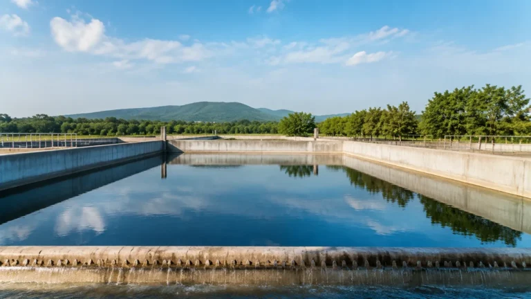
Carotek Matthews Nc
Carotek Matthews Nc
In the industrial landscape of the Southeastern United States, the coordination between high-quality manufacturing and regional engineering support is vital for operational efficiency. For process engineers and procurement specialists in North Carolina, the presence of localized expertise, such as that found at Carotek Matthews NC, serves as a critical bridge between advanced instrumentation technology and on-site application success. Level measurement, a cornerstone of process automation, requires a deep understanding of both the physical principles of sensing and the specific environmental challenges of the facility.
Selecting the right level measurement instrument involves more than just identifying a price point; it requires a technical evaluation of media characteristics, tank geometry, and integration requirements. This guide explores the fundamental technologies provided by global manufacturers like Welk and how they are implemented through professional regional support channels to ensure long-term reliability in water treatment, chemical processing, and oil and gas applications.
Understanding Level Measurement Principles
Before selecting a specific device, it is essential to understand the physics behind the various measurement technologies. Each method has distinct advantages depending on the state of the media (liquid, solid, or slurry) and the atmospheric conditions within the vessel.
Radar Level Measurement (ToF)
Radar level meters operate on the Time of Flight (ToF) principle. The sensor emits a high-frequency electromagnetic pulse—typically at 26GHz or 80GHz—which travels at the speed of light. When the pulse hits the surface of the medium, it is reflected back to the sensor. The instrument calculates the distance based on the time interval between emission and reception.
* Non-Contact Radar: Ideal for corrosive or hygienic applications where the sensor should not touch the media. The 80GHz variants offer a narrower beam angle, which is crucial for avoiding internal tank obstructions like agitators or heating coils.
* Guided Wave Radar (GWR): Uses a probe (cable or rod) to guide the signal. This is highly effective for low dielectric constant liquids and applications with heavy foam or turbulence.
Ultrasonic Level Sensors
Ultrasonic sensors use mechanical sound waves instead of electromagnetic waves. The transducer emits an ultrasonic pulse that reflects off the liquid surface. Because the speed of sound is influenced by air temperature, these sensors include built-in temperature compensation.
Ultrasonic technology is a standard choice for open-channel flow and atmospheric water tanks. However, it is generally not recommended for vacuum applications or environments with high dust and heavy steam, as these conditions can attenuate the sound wave.
Hydrostatic Pressure Level Transmitters
Hydrostatic measurement relies on the principle that the pressure at a specific depth in a liquid is proportional to the height of the liquid column above it. The formula $P = \rho \cdot g \cdot h$ (where $P$ is pressure, $\rho$ is density, $g$ is gravity, and $h$ is height) governs this technology. These transmitters are submerged or mounted to the bottom of a tank and are favored for their simplicity and reliability in deep wells and large storage tanks.
Magnetic Level Gauges
Magnetic level gauges provide both a visual indication and a signal output. A float containing a high-intensity magnet moves with the liquid level inside a bypass chamber. This magnet flips individual flags on an external scale and can also trigger reed switches or transmitters for remote monitoring. They are exceptionally robust for high-pressure and high-temperature boiler applications.
The Role of Regional Support in Matthews, NC
For facilities operating in the Charlotte metropolitan area and beyond, the technical support provided by entities like Carotek Matthews NC is indispensable. While a manufacturer like Welk focuses on the precision engineering and production of the sensors, regional experts provide the localized application engineering necessary to ensure the hardware fits the specific environmental constraints of the North Carolina industrial sector.
Local support involves:
1. Site Surveys: Evaluating the physical installation constraints, such as nozzle sizes and overhead clearance.
2. Configuration Services: Pre-configuring the 4-20mA HART, Modbus, or Profibus outputs to match the facility’s existing PLC/SCADA systems.
3. Emergency Inventory: Providing rapid access to replacement parts or backup units to minimize downtime in critical processes.
For a comprehensive review of available industrial instrumentation and to explore technical specifications for various sensor types, engineers are encouraged to visit the Main Page of our primary resource center.
Practical Selection Table
Choosing the correct technology requires balancing performance requirements with budget constraints. The following table provides a general comparison of the most common level measurement technologies.
| Technology | Media Type | Max Range | Typical Accuracy | Key Advantage | Best Application |
| :— | :— | :— | :— | :— | :— |
| 80GHz Radar | Liquids/Solids | 120m (393ft) | ±1mm | Narrow beam, high precision | Narrow silos, chemical reactors |
| 26GHz Radar | Liquids | 30m (98ft) | ±3mm | Reliable, cost-effective | General chemical storage |
| Ultrasonic | Liquids | 15m (49ft) | ±0.25% | Non-contact, low cost | Water treatment, sumps |
| Hydrostatic | Liquids | 200m (656ft) | ±0.1% | Simple installation | Deep wells, fuel tanks |
| Magnetic Gauge| Liquids | 6m (20ft) | ±5mm | Visual local indication | Boilers, oil-water separators |
Installation Considerations and Best Practices
Even the most advanced level meter will fail if installed incorrectly. When working with instrumentation from Welk or sourcing through regional partners like Carotek Matthews NC, follow these engineering guidelines:
1. Nozzle Placement and Geometry
For radar and ultrasonic sensors, the nozzle should be located away from the tank wall to prevent signal interference (false echoes). A general rule is to place the sensor at least 200mm (approx. 8 inches) away from the wall for every 1 meter (3.3 feet) of tank height. Ensure the sensor has a clear "line of sight" to the surface, avoiding ladders, pipes, or agitator blades.
2. The Dead Zone (Blocking Distance)
Every non-contact sensor has a "dead zone" directly beneath the transducer where measurement is impossible. For ultrasonic sensors, this might be 0.25m to 0.5m (10 to 20 inches). Ensure the maximum expected liquid level does not enter this zone, or use a nozzle extension if necessary.
3. Turbulence and Foam
Heavy foam can absorb ultrasonic and radar signals, leading to signal loss. In such cases, a Guided Wave Radar (GWR) or a stilling well is recommended. A stilling well is a vertical pipe installed inside the tank that provides a calm surface for the measurement, shielding the sensor from turbulence caused by inflows or mixers.
4. Atmospheric Compensation
In pressurized tanks, hydrostatic transmitters must be "balanced." This is typically done using a differential pressure (DP) transmitter or a vented cable that allows the sensor to reference the atmospheric pressure above the liquid, ensuring that changes in tank pressure do not result in false level readings.

Limitations and Common Risks
While modern instrumentation is highly advanced, certain environmental factors can still pose risks to accuracy:
* Dielectric Constant ($ε_r$): Radar relies on the reflectivity of the medium. Materials with a very low dielectric constant (like certain oils or liquefied gases) reflect less energy. In these scenarios, Guided Wave Radar is often the only viable non-contact-adjacent solution.
* Condensation and Buildup: In high-humidity environments, condensation can form on the face of an ultrasonic or radar transducer. Welk radar meters often utilize PTFE or PEEK antenna covers to shed moisture, but periodic cleaning may still be required in extreme "sticky" media applications.
* Temperature Extremes: Standard ultrasonic sensors are limited by the speed of sound changing in different gas densities. For high-temperature steam applications (above 80°C / 176°F), radar or magnetic gauges are significantly more reliable.
Frequently Asked Questions (FAQ)
Q: How do I choose between 26GHz and 80GHz radar?
A: 80GHz radar is preferred for smaller tanks or tanks with internal obstructions because its beam is much narrower. 26GHz is often sufficient for large, open storage tanks and can be more cost-effective for simple applications.
Q: Can hydrostatic sensors be used in tanks with varying density?
A: Hydrostatic sensors measure the weight of the liquid. If the density changes (due to temperature or mixing different chemicals), the level reading will change even if the physical height remains the same. If density is not constant, a radar sensor is a better choice.
Q: What maintenance is required for magnetic level gauges?
A: Magnetic gauges are low-maintenance, but the bypass chamber should be flushed periodically if the liquid contains solids or particulates that could cause the float to stick.
Q: Is it possible to integrate these sensors with a wireless network?
A: Yes, many modern level transmitters can be equipped with WirelessHART or LoRaWAN adapters, allowing for remote monitoring in locations where running signal cable is cost-prohibitive.
Conclusion
Successful level measurement in industrial environments is the result of combining robust hardware with expert application knowledge. Whether you are upgrading a water treatment plant or managing a complex chemical process, understanding the technical nuances of radar, ultrasonic, and hydrostatic technologies is the first step toward optimization. By leveraging the manufacturing excellence of Welk and the regional expertise available through partners like Carotek Matthews NC, facilities can ensure their level measurement systems provide accurate, repeatable data for years to come. For further technical documentation and product selection tools, please refer to the Main Page of our instrumentation guide.