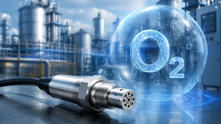
Ultrasonic Open Channel Flow Meter
Ultrasonic Open Channel Flow Meter
In industrial water management and wastewater treatment, measuring the volume of liquid moving through non-pressurized conduits is a critical requirement. Unlike closed-pipe systems where electromagnetic or ultrasonic transit-time meters are common, open channels—such as flumes, weirs, and partially filled pipes—require a different approach. The ultrasonic open channel flow meter has emerged as the industry standard for these applications due to its non-contact nature, ease of installation, and reliability in harsh environments. This guide provides a technical overview of how these systems function, how to select the correct components, and the best practices for installation and maintenance.
Understanding Ultrasonic Open Channel Flow Measurement
The measurement of flow in an open channel is an indirect process. It relies on the relationship between the liquid level (often called the "head") and the flow velocity within a standardized structure. An ultrasonic open channel flow meter system typically consists of three primary elements: the ultrasonic transducer (sensor), the electronic transmitter (controller), and the primary flow device (flume or weir).
The Measurement Principle
The ultrasonic sensor is mounted at a specific height above the liquid surface. It emits high-frequency sound pulses that travel through the air, reflect off the liquid surface, and return to the sensor. By measuring the time of flight—the time it takes for the pulse to travel to the surface and back—the transmitter calculates the distance to the liquid. Since the installation height of the sensor is known, the transmitter subtracts the measured distance from the total height to determine the current liquid level ($h$).
Once the level is known, the transmitter applies a mathematical formula specific to the geometry of the primary flow device. The general flow equation is expressed as:
$$Q = K \times h^n$$
Where:
* $Q$ is the flow rate (typically in m³/h or liters per second).
* $K$ is a constant derived from the dimensions of the flume or weir.
* $h$ is the measured head (liquid level).
* $n$ is an exponent that varies depending on the type of primary device (e.g., 1.5 for a rectangular weir, 2.5 for a V-notch weir).
Advanced transmitters, such as those available through the Main Page of specialized manufacturers like Welk, come pre-programmed with standard flow curves for various flumes and weirs, simplifying the commissioning process.
Primary Flow Devices: Weirs and Flumes
To achieve accurate flow measurement, the channel must have a known hydraulic characteristic. This is achieved by installing a primary device that creates a predictable relationship between level and flow.
Weirs
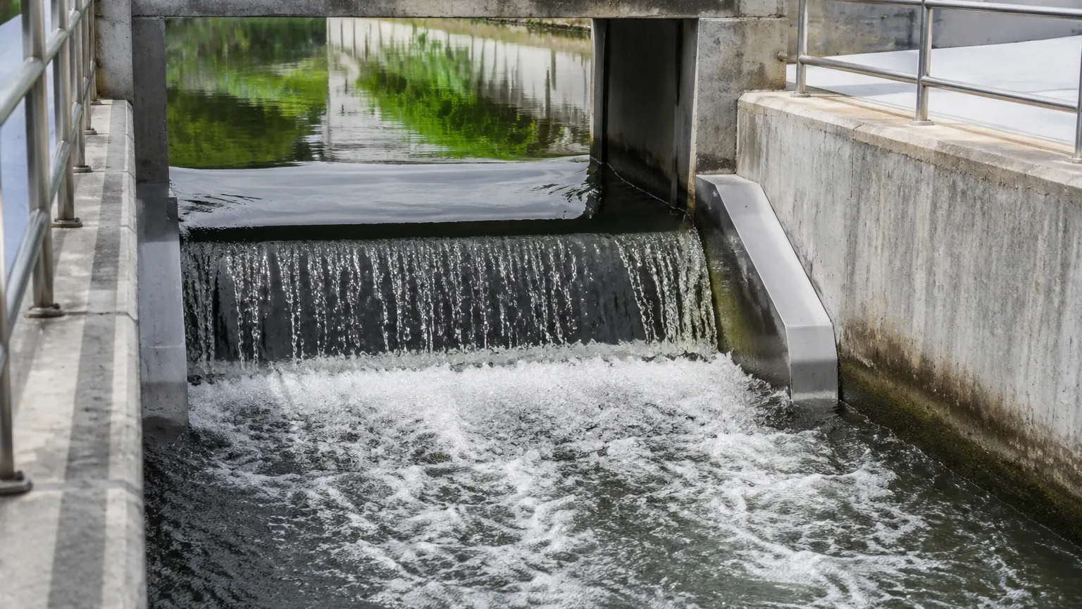
Weirs are essentially obstructions or dams placed across an open channel. They are most effective in clean water applications where there is minimal debris that could get trapped behind the weir plate.
* V-Notch (Triangular) Weirs: Best for low flow rates and high precision. Common angles are 22.5°, 45°, 60°, and 90°.
* Rectangular Weirs: Suitable for higher flow rates. They can be suppressed (spanning the full channel width) or contracted.
Flumes
Flumes are shaped structures that constrict the flow, causing a change in level. They are preferred for wastewater or liquids containing solids because they are "self-cleaning" and cause less head loss than weirs.
* Parshall Flumes: The most widely used flume globally, recognized for its ability to handle high-velocity flows and its tolerance for submergence.
* Palmer-Bowlus Flumes: Often used in existing circular sewer pipes or conduits because of their round-bottom design.
* Khafagi-Venturi Flumes: Commonly used in international industrial standards for sewage treatment plants.
| Device Type | Best Application | Accuracy | Head Loss |
| :— | :— | :— | :— |
| V-Notch Weir | Low flow, clean water | High | High |
| Rectangular Weir | Medium to high flow | Medium | High |
| Parshall Flume | Wastewater, large channels | High | Low |
| Palmer-Bowlus | Circular pipes, sewers | Medium | Low |
Key Components of an Ultrasonic Flow System
When specifying an ultrasonic open channel flow meter, engineers must consider the technical capabilities of both the sensor and the transmitter.
1. The Ultrasonic Transducer
The transducer's frequency determines its range and resolution. Higher frequencies (e.g., 60-80 kHz) offer better resolution for short-range measurements (up to 3-5 meters), while lower frequencies (e.g., 20-40 kHz) are used for longer distances or in environments with dust and steam. A critical factor is the Dead Zone (or blocking distance), which is the area immediately below the sensor where measurement is impossible. This usually ranges from 0.2m to 0.5m (approx. 8 to 20 inches).
2. The Transmitter/Controller
The transmitter processes the signal, performs temperature compensation (sound speed varies with air temperature), and provides the output. Standard industrial outputs include 4-20mA, RS485 (Modbus RTU), and relay outputs for totalizing flow or triggering samplers. Modern units often feature data logging capabilities to record historical flow trends.
3. Temperature Compensation
Because the speed of sound in air changes by approximately 0.17% per degree Celsius, an integrated temperature sensor within the ultrasonic transducer is essential for maintaining accuracy in outdoor installations where temperatures fluctuate throughout the day.
Selection Criteria for Industrial Applications
Choosing the right system requires a thorough understanding of the site conditions. Engineers should confirm the following parameters before procurement:
1. Maximum and Minimum Flow Rates: The system must be sized to handle the peak expected flow without overtopping the primary device, while remaining sensitive enough to measure minimum night-time flows.
2. Channel Dimensions: The width and depth of the channel determine the size of the flume or weir required.
3. Fluid Characteristics: Is the liquid corrosive? Does it produce foam? Ultrasonic pulses can be absorbed by thick foam, leading to false readings. In such cases, specialized sensors or stilling wells may be required.
4. Environmental Conditions: Will the sensor be exposed to direct sunlight, high winds, or heavy steam? These factors can affect the accuracy of the ultrasonic signal.
5. Power Supply: Standard options include 24V DC for integration into PLC systems or 110/220V AC for standalone installations.
Installation Best Practices and Considerations
Correct installation is more important than the instrument's inherent accuracy. Even the most precise ultrasonic open channel flow meter will fail to provide reliable data if positioned incorrectly.
Sensor Positioning
* Perpendicularity: The sensor must be mounted perfectly perpendicular to the liquid surface. A tilt of even a few degrees can cause the signal to bounce away from the receiver, resulting in a "Lost Echo" error.
* Location Relative to the Device: For a Parshall flume, the level should be measured at a point 2/3 of the length of the converging section upstream from the throat. For weirs, the sensor should be placed upstream at a distance of 3 to 4 times the maximum head ($h_{max}$) to avoid the "drawdown" effect near the crest.
* The Dead Zone: Ensure the sensor is mounted high enough so that even at maximum flow, the liquid level never enters the dead zone.
Upstream and Downstream Requirements
To ensure laminar flow (smooth, non-turbulent flow), there should be a straight run of channel upstream of the primary device. Typically, this should be at least 5 to 10 times the channel width. Similarly, the downstream section must be clear to prevent "backwater" effects, where water backs up into the flume and causes a false high-level reading.
Avoiding Interference
* Internal Obstructions: Ensure there are no pipes, ladders, or brackets within the ultrasonic beam's path. The beam typically spreads in a cone shape (usually 5° to 12°).
* Wind and Sun: In outdoor applications, using a sunshade or wind shield can prevent temperature gradients and air turbulence from distorting the signal.
Limitations and Environmental Factors
While ultrasonic technology is versatile, it is not a universal solution. Engineers must be aware of its limitations:
* Foam: Heavy, thick foam acts as an acoustic insulator, absorbing the ultrasonic pulse rather than reflecting it. If foam is persistent, a hydrostatic level transmitter or a radar-based level meter may be a better alternative.
* Steam and Vapors: Dense steam can change the composition of the air, altering the speed of sound and causing significant errors.
* Turbulence: Extreme surface turbulence can scatter the ultrasonic signal. Using a stilling well—a vertical pipe that dampens surface movement—can mitigate this issue.
* Vacuum: Ultrasonic meters cannot work in a vacuum because sound waves require a medium (air) to travel through.
Maintenance and Troubleshooting
One of the primary advantages of the ultrasonic open channel flow meter is the low maintenance requirement due to the lack of moving parts. However, periodic checks are necessary to ensure system integrity.
1. Transducer Cleaning: In humid environments, condensation or spider webs can accumulate on the transducer face. A simple wipe with a soft cloth is usually sufficient.
2. Zero-Point Verification: Periodically check the "distance to empty" setting when the channel is dry or at a known level to ensure the sensor hasn't shifted.
3. Debris Removal: For weir installations, ensure that no debris has accumulated behind the weir plate, as this changes the hydraulic characteristics and leads to over-reporting of flow.
4. Calibration: Annual calibration using a manual dipstick measurement compared against the transmitter's reading is recommended for regulatory compliance.
Frequently Asked Questions (FAQ)
Q: Can I use an ultrasonic flow meter in a pipe that is only partially full?
A: Yes, provided you use a primary device like a Palmer-Bowlus flume designed for circular conduits, or if the transmitter supports "Area-Velocity" calculations (which may require an additional velocity sensor).
Q: What is the typical accuracy of an ultrasonic open channel flow meter?
A: Under ideal conditions with a correctly installed flume, the system accuracy is typically between ±2% to ±5% of the flow rate. The ultrasonic sensor itself usually has an accuracy of ±0.25% of the measured distance.
Q: How do I handle applications with high chemical vapors?
A: For corrosive environments, ensure the transducer is made from chemically resistant materials like PVDF or PTFE. If the vapors are heavy enough to affect sound speed, consider switching to a radar level transmitter, which is unaffected by gas composition.
Q: Is it possible to measure flow without a flume or weir?
A: It is possible using the Manning Equation if the channel slope, roughness, and dimensions are perfectly consistent, but this is significantly less accurate than using a primary device and is generally not recommended for billing or regulatory reporting.
For engineers and facility managers looking to implement or upgrade their flow monitoring systems, selecting a partner with a robust portfolio of industrial instruments is essential. For more information on specific sensor models and technical support, visit the Main Page of Welk's industrial measurement division. Proper technology selection, combined with adherence to hydraulic principles, ensures that your open channel flow data remains accurate and actionable for years to come.