Autosampler
Autosampler
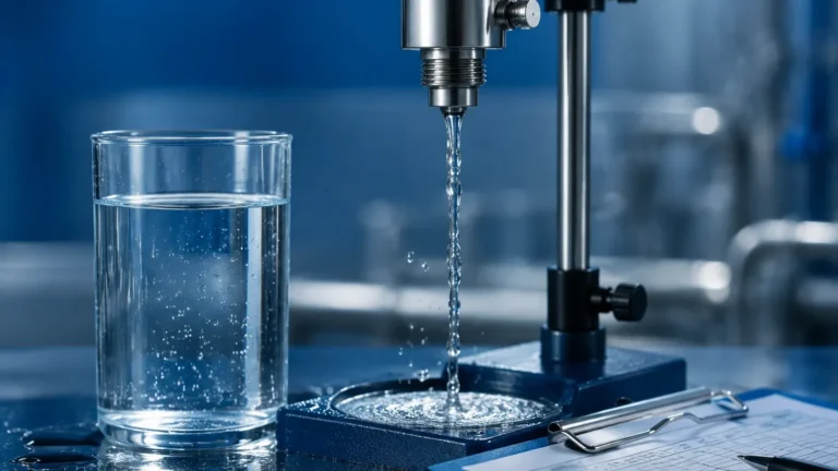
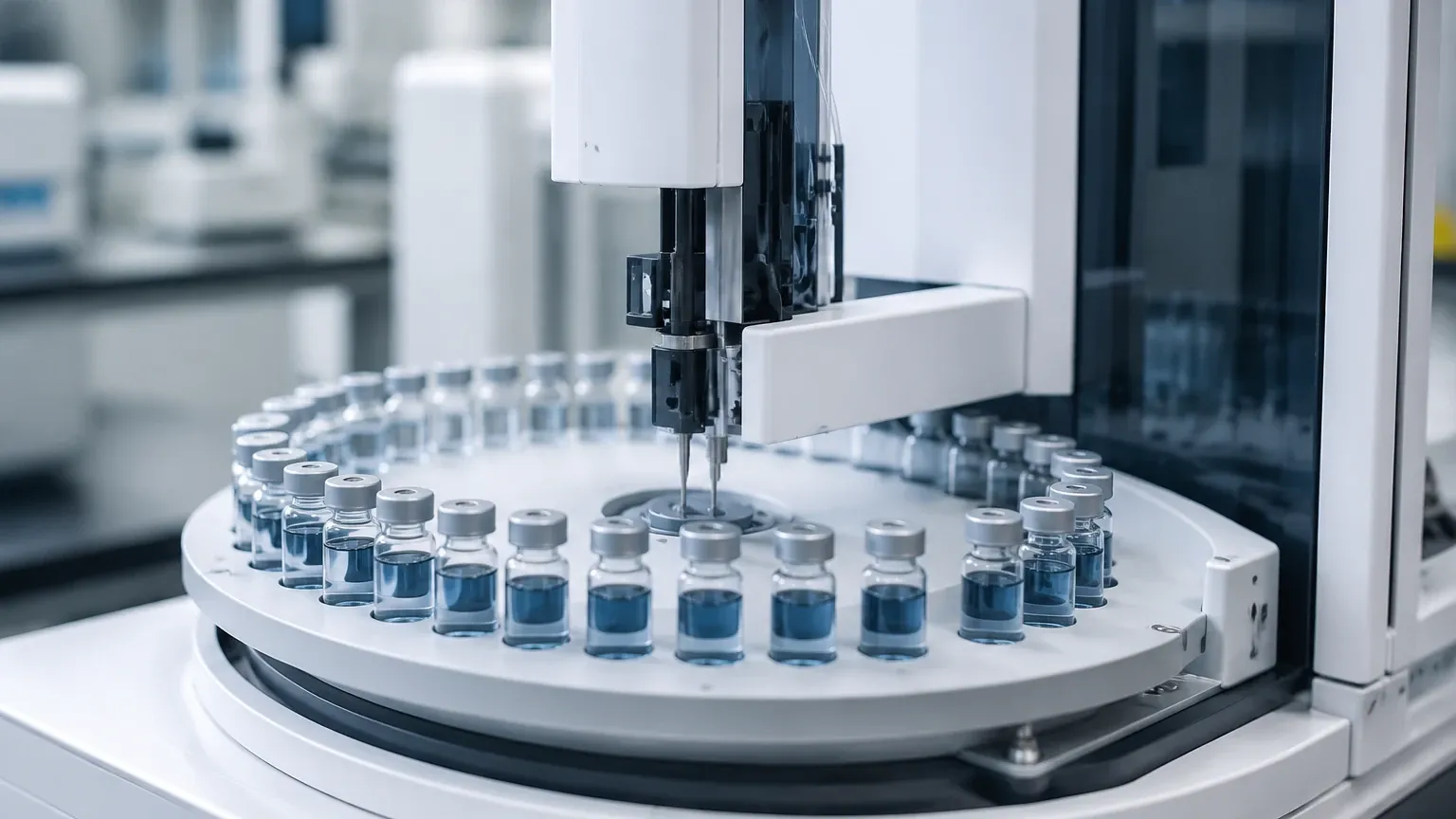
In the realm of industrial process control and environmental monitoring, the ability to collect representative liquid samples is as critical as the continuous monitoring of tank levels. An autosampler is a specialized instrument designed to collect discrete or composite liquid samples from a source—such as a wastewater stream, a chemical reactor, or an open channel—at predetermined intervals or in response to specific process triggers.
For engineers and plant operators, the effectiveness of an autosampler is often inextricably linked to the accuracy of level measurement instrumentation. Without precise data regarding the volume or flow rate of the medium, the samples collected may not accurately represent the process conditions. This guide examines the technical principles of automated sampling, its integration with level measurement technologies, and the criteria for selecting the appropriate system for industrial applications.
Principles of Operation and Integration
To understand the role of an autosampler, one must first understand the measurement principles that govern its triggers. Most industrial sampling protocols rely on either time-weighted or flow-weighted logic. In flow-weighted sampling, the autosampler requires real-time data from level sensors to calculate discharge rates through flumes or weirs.
Level Measurement Technologies in Sampling
Before an autosampler can be commissioned, the underlying level measurement technology must be established. The following instruments, often sourced from specialized manufacturers like Welk, provide the foundational data for automated sampling systems:
1. Radar Level Meters: These instruments utilize high-frequency microwave pulses (typically in the 26GHz or 80GHz range). The time-of-flight between emission and reception is used to calculate the distance to the liquid surface. In sampling applications, radar is preferred for its non-contact nature, making it immune to changes in density, temperature, or the presence of corrosive vapors.
2. Ultrasonic Level Sensors: Similar to radar but using sound waves, ultrasonic sensors are cost-effective solutions for open-channel flow measurement. They are frequently used to monitor the head level in primary flow elements (flumes), providing the 4-20mA signal that tells the autosampler when to initiate a suction cycle.
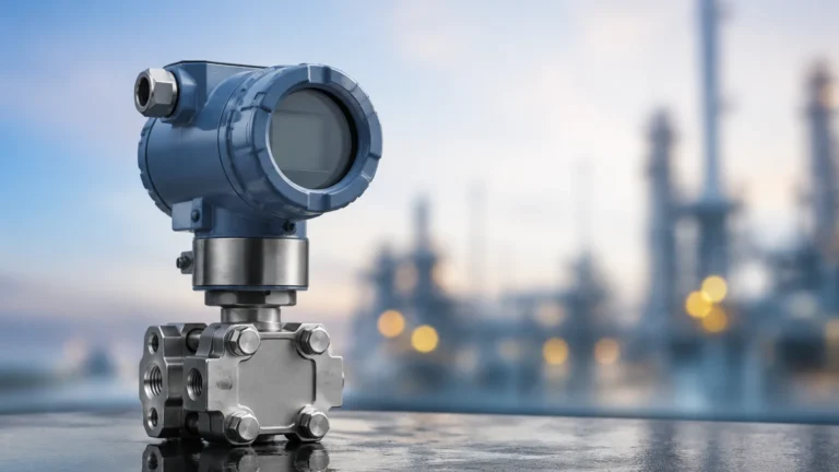
3. Hydrostatic Level Transmitters: These sensors measure the pressure exerted by the liquid column. They are particularly useful in deep wells or tanks where overhead space is limited. The pressure reading is converted into a level measurement, ensuring the sampling intake remains submerged at the correct depth.
The Sampling Mechanism
Once the level or flow trigger is met, the autosampler employs a mechanical system to extract the liquid. The most common methods include:
* Peristaltic Pumps: These use rotating rollers to compress a flexible tube, creating a vacuum that draws the sample up. This method is preferred for its ability to handle suspended solids without clogging the pump mechanism.
* Vacuum Suction: A vacuum pump exhausts air from a sampling chamber, drawing the liquid in. This is often faster than peristaltic methods and is suitable for high-lift applications (up to 7 or 8 meters).
Key Evaluation Criteria for Industrial Autosamplers
Selecting the right system requires a balance between the physical properties of the medium and the regulatory requirements for data reporting. When evaluating options, consider the following technical specifications:
Sample Preservation and Cooling
In many environmental applications, samples must be maintained at a specific temperature (typically 4°C) to prevent biological degradation or chemical changes. Stationary autosamplers often feature integrated refrigeration units, whereas portable units may rely on ice compartments. For industrial automation, ensuring the cooling system can withstand ambient temperatures exceeding 40°C is vital.
Programming Flexibility
Modern systems must support complex sampling routines. This includes "Event-Based Sampling," where the unit remains idle until a level sensor detects an overflow or a sudden spike in tank volume. Integrating these triggers requires a robust interface between the autosampler controller and the level transmitter's output.
Material Compatibility
The wetted parts of the sampling system—including the suction line, pump tubing, and sample bottles—must be chemically compatible with the process fluid. For corrosive chemical applications, PTFE (Teflon) or specialized elastomers are required to prevent contamination and equipment failure.
Selection Table: Autosampler and Level Integration
| Feature | Portable Autosampler | Stationary Autosampler | High-Lift Vacuum Sampler |
| :— | :— | :— | :— |
| Primary Use | Field studies, temporary monitoring | Permanent plant installation | Deep wells, high-rise tanks |
| Power Source | Battery (12V DC) | Mains (110V/220V AC) | Mains (High torque required) |
| Cooling | Passive (Ice) | Active Refrigeration | Active Refrigeration |
| Level Trigger | Ultrasonic (External) | Radar or Hydrostatic | Hydrostatic (Submerged) |
| Max Suction Lift | 6 – 7 meters | 7 – 8 meters | Up to 9 meters |
| Sample Volume | 20ml to 1000ml | 10ml to 10,000ml | 50ml to 5000ml |
Installation and Engineering Considerations
Proper installation is the difference between a reliable data set and a failed compliance audit. Engineers should prioritize the following factors during the design phase:
Positioning the Intake
The suction line must be positioned in a zone of high turbulence to ensure the sample is representative of the entire flow. However, it should not be placed so low that it draws in settled solids from the bottom of a tank, nor so high that it draws in floating oils or debris. Utilizing a hydrostatic level transmitter can help maintain the intake at a fixed offset from the liquid surface.
Suction Line Dynamics
The length and diameter of the suction line significantly impact the velocity of the sample. To prevent the settling of solids within the tube, a minimum transport velocity of 0.6 m/s (2.0 ft/s) is generally recommended. If the distance between the sampling point and the unit is excessive, the pump may struggle to maintain this velocity, leading to biased samples.
Integration with Level Meters
For flow-proportional sampling, the autosampler must receive a pulse or 4-20mA signal from a flow meter or level sensor. When selecting instrumentation from the Main Page, ensure the sensor supports the necessary communication protocols (such as Modbus or HART) to interface directly with the autosampler's controller. This integration ensures that for every X cubic meters of fluid measured, a specific volume of sample is collected.
Common Risks and Limitations
While automated sampling increases efficiency, it is not without risks. Understanding these limitations is essential for long-term reliability.
1. Cross-Contamination: If the system does not perform a sufficient "pre-purge" (blowing air through the line before sampling) and "post-purge" (clearing the line after sampling), remnants of the previous sample may contaminate the current one.
2. Tube Wear: In peristaltic pumps, the constant mechanical stress on the tubing leads to eventual failure. A preventative maintenance schedule must be established to replace tubing before it ruptures.
3. Representative Bias: If the sampling velocity is lower than the flow velocity of the stream, larger particles may be under-represented in the sample. This is known as non-isokinetic sampling and is a common concern in heavy industrial wastewater.
4. Signal Interference: In environments with heavy machinery, electrical noise can interfere with the signal between the level sensor and the autosampler. Using shielded cables and proper grounding is mandatory.
Frequently Asked Questions (FAQs)
Q: Can an autosampler be used in hazardous (Ex) areas?
A: Yes, but the unit must be specifically rated for the zone (e.g., ATEX or IECEx). Many stationary refrigerated samplers are not rated for hazardous areas and must be placed in a non-classified control room with the suction line extended into the hazardous zone.
Q: How often should the level sensor triggering the sampler be calibrated?
A: For compliance-related sampling, level sensors should be checked quarterly. If the level reading drifts by even 2-3%, the resulting flow-proportional sample volume could be significantly inaccurate.
Q: What is the maximum distance an autosampler can be from the liquid source?
A: While some units can pull liquid from 30 meters away horizontally, the vertical lift is the limiting factor. Most pumps cannot exceed a vertical lift of 8 meters (approx. 26 feet) due to the physical limits of atmospheric pressure and vacuum generation.
Q: How do I handle samples with high solids content?
A: Use a wide-bore suction line (at least 12mm or 1/2 inch) and a high-speed peristaltic pump. Ensure the level sensor is a non-contact radar to avoid fouling from the solids.
Conclusion
An autosampler is a vital component of modern industrial monitoring, providing the physical evidence needed to validate the continuous data provided by level and flow sensors. By integrating high-quality level measurement instruments—such as those found on the Main Page—with a robust sampling strategy, facilities can achieve higher standards of process control and environmental compliance. When selecting a system, always prioritize the relationship between the measurement principle, the physical constraints of the installation site, and the chemical nature of the medium being sampled.