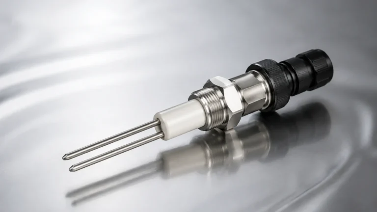
Heat Sensor Switch
Heat Sensor Switch
In industrial automation and process control, the heat sensor switch—often referred to as a thermal switch or temperature switch—serves as a critical safety and control component. These devices are designed to open or close an electrical circuit when a specific temperature threshold is reached. Unlike continuous temperature transmitters that provide a constant stream of data, a heat sensor switch operates on a binary principle, making it an essential tool for over-temperature protection, cooling system activation, and process sequencing.
For engineers and plant managers, understanding the mechanics and selection criteria of these switches is vital for maintaining the integrity of expensive equipment, including level measurement systems and pressurized vessels. This guide explores the fundamental principles, industrial applications, and technical considerations for integrating heat sensor switches into modern process environments.
Measurement Principles of Heat Sensor Switches
To select the appropriate heat sensor switch for a specific application, one must first understand the underlying physical principles that trigger the switching action. Most industrial switches fall into three primary categories based on their sensing technology.
Bimetallic Strips
The most common mechanical heat sensor switch utilizes a bimetallic strip. This component consists of two different metals bonded together, each with a distinct coefficient of thermal expansion. As temperature increases, one metal expands faster than the other, causing the strip to bend. When the temperature reaches a predetermined setpoint, the mechanical displacement is sufficient to snap a contact open or closed. These are robust, cost-effective, and do not require external power to operate the sensing element.
Thermistor-Based Switching
Electronic heat sensor switches often use thermistors (Thermal Resistors). These are ceramic or polymer semiconductors where resistance changes significantly with temperature.
- PTC (Positive Temperature Coefficient): Resistance increases as temperature rises.
- NTC (Negative Temperature Coefficient): Resistance decreases as temperature rises.
An integrated circuit monitors this resistance and triggers a relay or solid-state output when the threshold is crossed. These offer higher precision and narrower hysteresis than bimetallic versions.
Gas-Actuated and Liquid-Filled Systems
For heavy-duty industrial applications, particularly in hazardous areas, gas-actuated switches are used. A bulb filled with gas or liquid is connected via a capillary tube to a bellows or diaphragm. As the temperature at the bulb rises, the internal pressure increases, physically moving the diaphragm to actuate a microswitch. This method is highly reliable for high-temperature ranges and provides excellent mechanical force for switching high-current loads.
Industrial Applications and Level Measurement Integration
While a heat sensor switch is a standalone temperature device, its role is often intertwined with other process variables, such as level measurement. In tanks and reactors, temperature extremes can compromise the accuracy of level sensors or damage the instruments themselves.
Pump Protection and Dry-Run Prevention
In water treatment and chemical processing, pumps are often protected by a combination of level switches and heat sensor switches. If a level sensor fails to detect a low-fluid condition, the pump may run dry, leading to rapid heat buildup due to friction. A heat sensor switch mounted on the pump casing or discharge line acts as a secondary safety layer, shutting down the motor before catastrophic seal failure occurs.
Protecting Level Instrumentation
Advanced level measurement technologies, such as those found on the Main Page of industrial instrumentation catalogs, often have specific operating temperature limits. For instance, the electronics in an ultrasonic level sensor or the housing of a radar level meter may be rated for up to 80°C (176°F). In applications involving steam cleaning (CIP) or exothermic reactions, a heat sensor switch can trigger cooling fans or signal a PLC to retract or isolate sensitive probes when temperatures exceed safe limits.
Selection Criteria for Heat Sensor Switches
Choosing the right switch requires a balance between environmental conditions, electrical requirements, and the required response time. The following table provides a general comparison of common industrial heat sensor switch types.
| Feature | Bimetallic Switch | Thermistor Switch | Gas-Actuated Switch |
| :— | :— | :— | :— |
| Temperature Range | -50°C to +250°C | -40°C to +150°C | -100°C to +600°C |
| Accuracy | Moderate (±5°C) | High (±0.5°C) | Moderate (±2°C) |
| Response Time | Slow to Medium | Fast | Medium |
| Power Required | No | Yes | No |
| Durability | High (Mechanical) | Moderate (Electronic) | Very High (Heavy Duty) |
| Typical Use | Motor protection | Precision electronics | Petrochemical/Oil & Gas |
Key Evaluation Factors
1. Set Point and Hysteresis: The set point is the temperature at which the switch actuates. Hysteresis (or differential) is the temperature difference between the switch-on and switch-off points. High hysteresis prevents "chattering," where the switch rapidly toggles near the set point.
2. Contact Configuration: Determine if the application requires Normally Open (NO) or Normally Closed (NC) contacts. For safety-critical over-temperature protection, NC contacts are preferred because they provide a fail-safe signal if a wire is cut.
3. Environmental Rating: In chemical or outdoor environments, the switch housing must meet specific IP (Ingress Protection) ratings, such as IP65 or IP67, and may require explosion-proof certification (ATEX/IECEx) for hazardous zones.
Installation Considerations and Best Practices
Proper installation is critical to ensure that the heat sensor switch accurately reflects the process temperature rather than the ambient environment.
Mounting Location
The sensor must be placed where the heat source is most representative of the risk. In a liquid tank, this is usually submerged near the heating element or the process outlet. For motor protection, the switch should be in direct contact with the windings or the bearing housing.
Thermal Conductivity
Air is a poor conductor of heat. If the switch is surface-mounted, using thermal conductive paste between the sensor face and the equipment surface can significantly reduce response lag. For immersion applications, ensure the thermowell or probe length is sufficient to avoid "stem conduction" errors, where the ambient temperature outside the tank cools the sensor tip.
Wiring and Interference
For electronic heat sensor switches, shielded cabling is recommended to prevent electromagnetic interference (EMI) from high-voltage motors or VFDs (Variable Frequency Drives) from causing false trips. Mechanical switches are less susceptible to EMI but require robust terminal connections to withstand industrial vibrations.
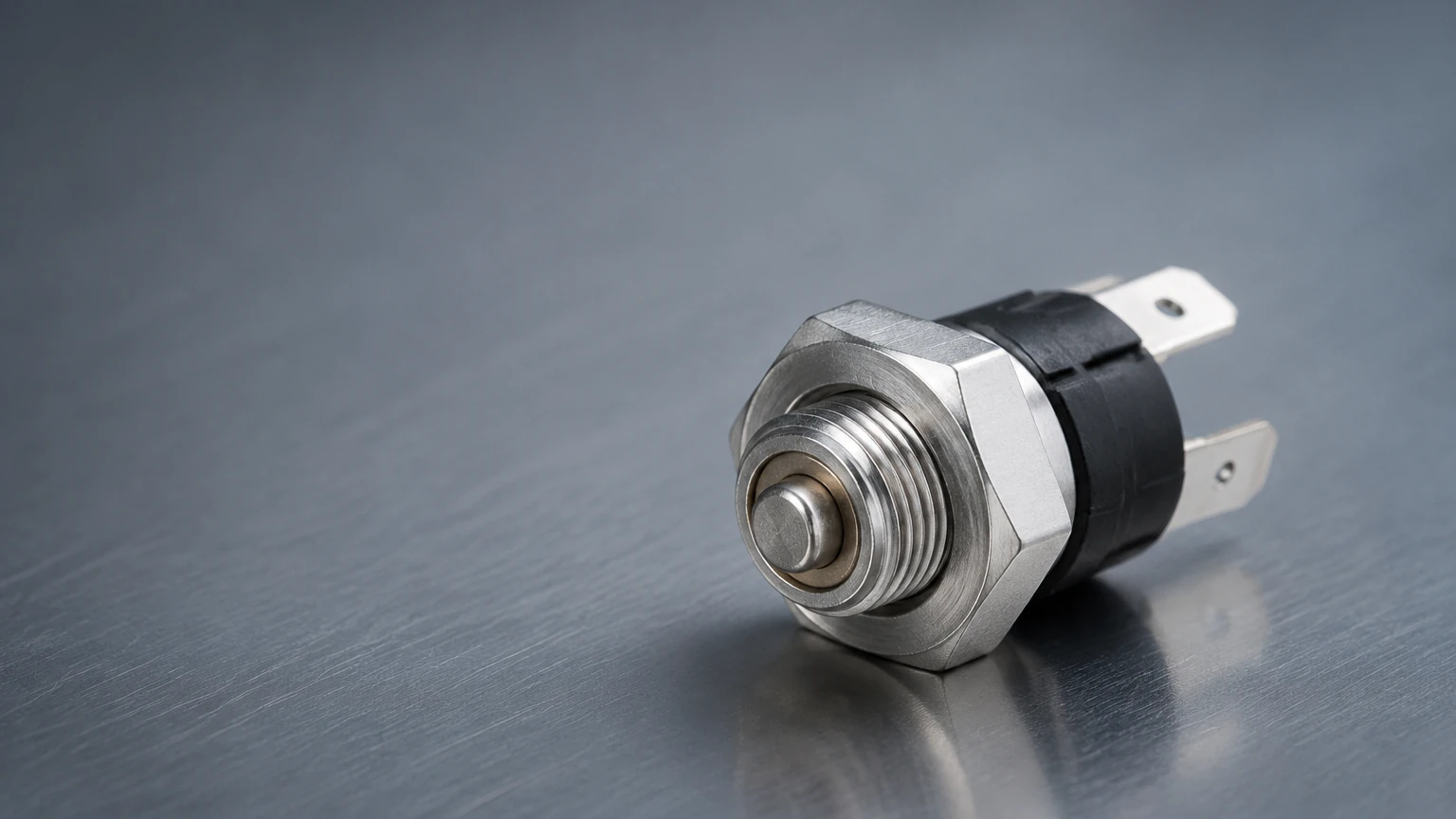
Limitations and Common Risks
While reliable, heat sensor switches are not without limitations. Engineers must account for the following risks during the design phase:
* Thermal Lag: There is always a delay between the process reaching a temperature and the internal sensing element of the switch reaching that same temperature. This lag must be factored into safety set points.
* Mechanical Fatigue: Bimetallic switches have a finite number of cycles. In applications with frequent temperature fluctuations, the metal strip may eventually lose its calibration or fail to snap.
* Calibration Drift: Over time, exposure to extreme temperatures or vibration can cause the set point to shift. Regular functional testing (checking the trip point with a calibrated heat source) is essential for safety-instrumented systems.
* Contact Pitting: Switching high-inductive loads (like large solenoids or motor starters) can cause arcing across mechanical contacts, leading to pitting and eventual sticking. Using an intermediate relay or an RC snubber circuit can extend the life of the switch.
Frequently Asked Questions (FAQs)
Q: Can a heat sensor switch be used to control a heater directly?
A: It depends on the current rating. Most small bimetallic switches are rated for 5A to 15A. For larger industrial heaters, the heat sensor switch should trigger a contactor or a Solid State Relay (SSR) rather than handling the full load current directly.
Q: What is the difference between a temperature switch and a temperature transmitter?
A: A switch provides a discrete (on/off) output at a specific limit. A transmitter provides a continuous analog (e.g., 4-20mA) or digital signal representing the actual temperature value across a range.
Q: How do I choose between a fixed and an adjustable set point?
A: Fixed set points are tamper-proof and ideal for standardized safety shut-offs. Adjustable switches are better for process development or applications where the optimal operating temperature might change based on the product being manufactured.
Conclusion
The heat sensor switch remains a cornerstone of industrial safety and process efficiency. By providing a reliable, hardware-based response to thermal changes, these devices protect both personnel and expensive assets like level measurement instruments and pumping systems. When selecting a switch, engineers should prioritize the physical measurement principle that best suits their accuracy requirements and environmental constraints.
For those managing complex fluid systems, integrating thermal protection with robust level control solutions ensures a comprehensive approach to plant automation. For further technical specifications on integrated measurement solutions, professionals often consult a dedicated Main Page of instrumentation to ensure all components—from level gauges to thermal overrides—work in harmony.