Inline Conductivity Probe
Inline Conductivity Probe
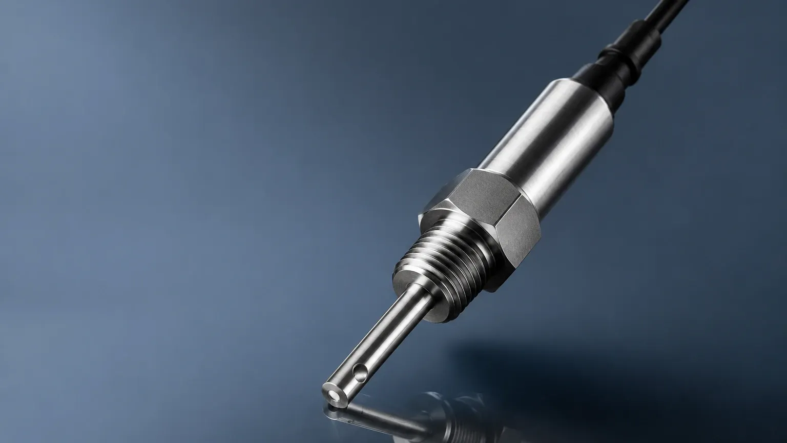
In industrial process control, the measurement of electrolytic conductivity is a fundamental requirement for assessing water quality, chemical concentration, and the presence of impurities. An inline conductivity probe is a precision instrument designed to measure the ability of a solution to conduct an electrical current while integrated directly into a piping system or process vessel. Unlike laboratory measurements, inline probes provide real-time data, enabling immediate adjustments in automated systems such as water treatment plants, chemical processing facilities, and food and beverage production lines.
Understanding the Principles of Conductivity Measurement
To effectively select and deploy an inline conductivity probe, it is essential to understand the underlying physics of how these sensors interact with a liquid medium. Conductivity is the reciprocal of electrical resistivity and is measured in Siemens per meter (S/m), though in industrial applications, microsiemens per centimeter (µS/cm) or millisiemens per centimeter (mS/cm) are the standard units.
Electrolytic Conduction
In metallic conductors, current is carried by electrons. In liquids, however, current is carried by dissolved ions (cations and anions). The conductivity of a solution depends on the concentration of these ions, their mobility, and their valence. Since pure water is a very poor conductor, any increase in conductivity typically indicates an increase in dissolved solids or chemical concentration.
The Cell Constant (k)
Every conductivity sensor has a specific geometry defined by the area of the electrodes (A) and the distance between them (L). The ratio of the distance to the area is known as the cell constant ($k = L/A$).
* Low Cell Constants (k=0.01 to 0.1 cm⁻¹): These sensors have large, closely spaced electrodes. They are designed for high sensitivity in low-conductivity fluids, such as ultrapure water or boiler condensate.
* Standard Cell Constants (k=1.0 cm⁻¹): These are general-purpose sensors used for potable water and medium-range process fluids.
* High Cell Constants (k=10 cm⁻¹ or higher): These sensors have small electrodes spaced further apart, making them suitable for high-conductivity liquids like seawater, brine, or concentrated acids.
Temperature Compensation
Conductivity is highly temperature-dependent. As the temperature of a solution rises, the viscosity typically decreases, and ionic mobility increases, leading to higher conductivity readings even if the chemical concentration remains the same. Most industrial fluids exhibit a change of approximately 2% per degree Celsius. For accurate process control, an inline conductivity probe must incorporate an integrated temperature sensor (usually a Pt100 or Pt1000 RTD) to provide temperature-compensated readings, typically referenced to 25°C.
Types of Inline Conductivity Probes and Sensor Technologies
There are two primary technologies used for inline conductivity measurement: contacting (electrode-based) and inductive (toroidal).
1. Contacting Conductivity Sensors
Contacting sensors utilize electrodes that come into direct physical contact with the process fluid. They are further divided into two-electrode and four-electrode configurations.
* Two-Electrode Sensors: A known AC voltage is applied between two electrodes, and the resulting current is measured. While simple and cost-effective, they are susceptible to "polarization error" at high conductivity levels and are sensitive to electrode fouling.
* Four-Electrode Sensors: These use two drive electrodes to create a current and two sensing electrodes to measure the voltage drop. This design eliminates the effects of polarization and lead wire resistance, making them more accurate across wider measurement ranges.
2. Inductive (Toroidal) Conductivity Sensors
Inductive sensors do not use electrodes. Instead, they consist of two wire-wound metal toroids encapsulated in a chemically resistant plastic (such as PEEK or PFA). One toroid acts as a transmitter, inducing an alternating current in the surrounding liquid. The second toroid acts as a receiver, measuring the magnitude of this current, which is proportional to the conductivity of the fluid.
Inductive probes are ideal for highly corrosive fluids, wastewater with high solids content, or applications where electrode coating is a frequent problem. Because there is no metal-to-liquid contact, they require significantly less maintenance than contacting probes.
Key Evaluation Criteria for Industrial Selection
Selecting the correct inline conductivity probe requires a detailed analysis of the process environment. Engineers should consult the Main Page for a broader view of how these sensors integrate with comprehensive process monitoring solutions. The following table summarizes the primary selection factors:
| Feature | Contacting (2-Pole) | Contacting (4-Pole) | Inductive (Toroidal) |
| :— | :— | :— | :— |
| Measurement Range | 0.01 µS/cm to 1,000 µS/cm | 10 µS/cm to 1 S/cm | 100 µS/cm to 2 S/cm |
| Best Application | Ultrapure water, DI water | General process water | Acids, bases, wastewater |
| Fouling Resistance | Very Low | Moderate | Very High |
| Material Options | SS316L, Titanium, Graphite | SS316L, Hastelloy | PEEK, PFA, PP |
| Installation Size | Small (1/2" to 1" NPT) | Small to Medium | Large (2" or larger) |
Material Compatibility
The wetted materials of the probe must be compatible with the process fluid. For pharmaceutical or food applications, 316L stainless steel with a high-polish finish (Ra < 0.8 µm) is standard. For aggressive chemicals like hydrochloric acid or sodium hypochlorite, non-metallic inductive probes are mandatory to prevent corrosion.
Pressure and Temperature Ratings
Inline probes must withstand the hydraulic forces of the piping system. Most industrial probes are rated for pressures up to 10–20 bar (145–290 psi) and temperatures up to 130°C–150°C. In high-temperature applications, such as Steam-In-Place (SIP) cycles in biotechnology, the probe must be designed to withstand thermal shock without losing calibration.
Installation Best Practices for Inline Probes
Proper installation is critical to ensuring the longevity and accuracy of an inline conductivity probe. Incorrect placement can lead to air entrapment or sediment buildup, both of which cause erroneous readings.
1. Orientation: The probe should ideally be installed in a vertical pipe with the flow moving upward. This ensures that the pipe is always full and that air bubbles—which are non-conductive—do not become trapped against the sensor surface. If horizontal installation is necessary, the probe should be mounted on the side of the pipe, not the top (where air collects) or the bottom (where sediment settles).
2. Flow Velocity: A minimum flow velocity is often required to keep the sensor surfaces clean. However, excessively high velocity can cause cavitation or physical wear on the electrodes. A steady flow between 0.5 m/s and 2.0 m/s is generally recommended.
3. Submergence: The active portion of the sensor (the electrodes or the toroidal opening) must be completely submerged in the fluid. For inductive probes, there must be sufficient clearance between the sensor head and the pipe wall (typically at least 20–30 mm) to avoid "wall effects" that interfere with the magnetic field.
4. Grounding: In plastic piping systems, electrical noise can interfere with conductivity measurements. Ensuring the transmitter and the process fluid are properly grounded is essential for stable readings.
Common Risks, Limitations, and Troubleshooting
While inline conductivity probes are robust, they are not immune to process-related challenges.
* Polarization: In contacting sensors, the accumulation of ions at the electrode surface can create a resistive layer, leading to artificially low conductivity readings. Using high-frequency AC drive signals and 4-electrode designs mitigates this risk.
* Scaling and Coating: In hard water or chemical precipitation applications, minerals can coat the electrodes. This increases the apparent resistance and lowers the measured conductivity. Regular cleaning with a mild acid or the use of an inductive sensor can solve this issue.
* Air Bubbles: As mentioned, air is an insulator. Even small micro-bubbles clinging to the electrode surface will significantly reduce the measured conductivity. Ensuring high back-pressure in the system can help keep gases dissolved in the liquid.
* Cable Interference: Conductivity signals, especially from high-impedance contacting sensors in low-conductivity water, are susceptible to electromagnetic interference (EMI). Always use shielded cables and keep them away from high-voltage power lines.
Integration with Industrial Level and Process Control Systems
In many industrial setups, conductivity measurement is used in conjunction with level measurement to provide a complete picture of tank or vessel status. For example, in a chemical mixing tank, a radar or ultrasonic level meter from a provider like Welk monitors the volume, while an inline conductivity probe ensures the chemical concentration is within the specified range.
Conductivity can also be used for interface detection. In systems where two liquids with different conductivities are stored in the same tank (such as oil and water), a conductivity probe can detect the transition point as the tank is drained, signaling a valve to close or divert the flow. This synergy between level and analytical measurement is a cornerstone of modern industrial automation.
Frequently Asked Questions (FAQ)
Q: How often should an inline conductivity probe be calibrated?
A: Calibration frequency depends on the application. In stable, clean water systems, once every six months may suffice. In aggressive chemical processes or where fouling is common, monthly or even weekly verification against a standard solution is recommended.
Q: Can I use a conductivity probe to measure the concentration of a specific acid?
A: Yes, provided it is a binary solution (e.g., just sulfuric acid and water). Since conductivity is a non-specific measurement (it measures all ions), it cannot distinguish between different chemicals in a complex mixture.
Q: What is the difference between "Conductivity" and "TDS"?
A: Total Dissolved Solids (TDS) is a measure of the mass of dissolved material in a volume of water. Conductivity is an electrical measurement. Most transmitters use a conversion factor (typically 0.5 to 0.7) to estimate TDS from conductivity: $TDS (mg/L) = Conductivity (µS/cm) \times Factor$.
Conclusion: Steps Before Procurement
Before selecting an inline conductivity probe, technical teams should confirm the following:
1. Chemical Composition: Identify all chemicals present to ensure material compatibility (e.g., PEEK vs. Stainless Steel).
2. Expected Range: Determine the minimum and maximum conductivity levels to select the correct cell constant.
3. Process Conditions: Confirm the maximum operating pressure and temperature, including cleaning cycles (CIP/SIP).
4. Pipe Geometry: Ensure there is adequate space for the probe, especially for larger inductive models.
By carefully matching the sensor technology to the specific demands of the process, facilities can achieve reliable, long-term monitoring that enhances both product quality and operational efficiency.