
Calibrate Flow Meter
Calibrate Flow Meter
In industrial process control, the accuracy of measurement instrumentation is the foundation of operational efficiency, safety, and fiscal accountability. Whether managing water treatment facilities, chemical processing plants, or oil and gas refineries, the ability to precisely calibrate flow meter units ensures that the data driving automated systems is reliable. Calibration is the formal process of comparing the readings of a flow measurement device against a traceable reference standard, identifying discrepancies, and adjusting the device to meet specified tolerance levels.
For engineers and plant managers, understanding the nuances of how to calibrate flow meter systems is not merely a maintenance task but a critical component of lifecycle management. This guide examines the principles of flow measurement, the methodologies for calibration, and the practical considerations required to maintain peak performance in demanding industrial environments.
Measurement Principles and Technology Overview
Before discussing calibration procedures, it is essential to understand the underlying physical principles of the flow meters being tested. Different technologies interact with the fluid in distinct ways, which dictates how they should be calibrated.
1. Velocity-Based Meters
Most modern flow meters, including electromagnetic and ultrasonic types, measure the velocity of the fluid and calculate the volumetric flow rate based on the cross-sectional area of the pipe ($Q = A \times v$).
- Electromagnetic Meters: Operate on Faraday’s Law of Induction. As a conductive fluid moves through a magnetic field, it generates a voltage proportional to its velocity.
- Ultrasonic Meters: Use transit-time or Doppler shift methods. Transit-time meters measure the time difference between signals sent upstream and downstream.
2. Differential Pressure (DP) Meters
These meters, such as orifice plates or Venturi tubes, rely on Bernoulli’s principle. By creating a constriction in the flow path, a pressure drop is generated. The square root of this pressure differential is proportional to the flow rate. Calibration for these systems often involves calibrating the DP transmitter rather than the primary element itself.
3. Positive Displacement (PD) Meters
PD meters measure the actual volume of the fluid by trapping it in rotating components (gears or pistons). These are highly accurate for viscous fluids and are often calibrated using volumetric or gravimetric standards.
4. Mass Flow Meters
Coriolis meters measure the mass flow directly by detecting the inertia caused by fluid flowing through oscillating tubes. These are often considered the "gold standard" for accuracy and are frequently used as master meters to calibrate flow meter units of other types.
Why Calibration is Essential
Over time, all mechanical and electronic sensors experience "drift." In flow measurement, this can be caused by:
- Mechanical Wear: Erosion of turbine blades or orifice plate edges.
- Scaling and Fouling: Buildup of minerals or biological matter on the interior walls of the meter, changing the internal diameter.
- Electronic Component Aging: Shift in the signal processing circuitry due to thermal cycling or moisture.
- Process Changes: Significant changes in fluid viscosity, density, or temperature that were not accounted for during the initial setup.
Regularly scheduled intervals to calibrate flow meter hardware ensure that the "as-found" data is documented and the "as-left" condition meets the required ±0.5% to ±2% accuracy typical of industrial applications.
Core Methodologies to Calibrate Flow Meter Systems
There are three primary methods used in both laboratory and field settings to verify and adjust flow meter accuracy.
1. Master Meter Calibration
This is the most common method for field calibration. A "master meter"—a device with high precision and a known, documented calibration curve—is placed in series with the unit under test (UUT).
- Process: The same fluid passes through both meters. The readings are compared across several flow points.
- Advantage: It allows for in-situ calibration without removing the meter from the process line, provided there is a bypass or a dedicated test port.
2. Gravimetric (Weight-Based) Calibration
Generally considered the most accurate method, gravimetric calibration involves diverting the flow into a container on a high-precision scale for a measured period.
- Process: The weight of the fluid is converted to volume (using the fluid's density) or compared directly if the UUT is a mass flow meter.
- Calculation: $\text{Flow Rate} = \frac{\text{Weight}}{\text{Time} \times \text{Density}}$.
- Advantage: It is an absolute measurement method, often used as the primary standard in calibration laboratories.
3. Volumetric (Prover) Calibration
This method uses a calibrated vessel (a prover) with a known volume.
- Process: Fluid is passed through the UUT into the prover. The level in the prover is read against a sight glass or electronic level sensor.
- Advantage: It is highly effective for calibrating liquid flow meters in the field, particularly in the oil and gas industry where "pipe provers" are common.
Selection Table: Calibration Methods Comparison
| Method | Typical Accuracy | Portability | Best Application |
| :— | :— | :— | :— |
| Master Meter | ±0.1% to ±0.5% | High | Field verification, non-critical process loops |
| Gravimetric | ±0.01% to ±0.1% | Low | Laboratory standards, custody transfer meters |
| Volumetric | ±0.1% to ±0.2% | Medium | Fuel loading, large scale water distribution |
| Clamp-on Ultrasonic| ±1.0% to ±3.0% | Excellent | Quick checks, non-invasive verification |
Step-by-Step Procedure to Calibrate Flow Meter
To ensure a successful calibration, a standardized procedure must be followed. While specific steps vary by meter type, the following general workflow applies to most industrial scenarios.
Step 1: Pre-Calibration Inspection
Before testing, inspect the meter for physical damage. Check the electrical connections and ensure the pipe is full (for liquid meters). If the meter has a built-in display, check for any error codes or diagnostic warnings.
Step 2: Zero-Flow Verification
Shut off the flow completely and ensure the pipe remains full. The meter should read exactly zero. If it does not, a "zero-point adjustment" is performed. This is a critical step for electromagnetic and Coriolis meters.
Step 3: Multi-Point Testing
Calibration should never be done at a single flow rate. A standard calibration typically involves at least five points across the meter’s operating range (e.g., 10%, 25%, 50%, 75%, and 100% of maximum flow).
- Allow the flow to stabilize at each point for several minutes.
- Record the reading from the UUT and the reference standard simultaneously.
Step 4: Data Analysis and Adjustment
Calculate the error at each point:
$$\text{Error \%} = \frac{(\text{UUT Reading} – \text{Reference Reading})}{\text{Reference Reading}} \times 100$$
If the error exceeds the manufacturer's specification, adjust the meter's "K-factor" or scaling constant. For digital meters, this is done via the transmitter software interface.
Step 5: Post-Adjustment Verification
After adjustments are made, repeat the multi-point test to ensure the meter now reads within the acceptable tolerance. Document these as the "as-left" values.
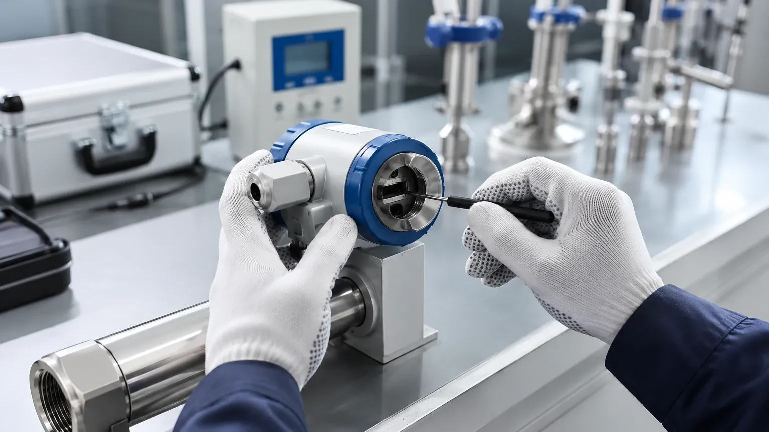
Installation Considerations for Accurate Calibration
Calibration is only valid if the installation conditions in the field match the requirements of the meter. Even a perfectly calibrated meter will provide false data if installed incorrectly.
1. Straight Pipe Runs: Most meters require a specific length of straight pipe upstream (typically 10 diameters) and downstream (5 diameters) to eliminate turbulence and swirl. If these are not present, flow conditioners may be required.
2. Fluid State: Ensure there are no air bubbles in liquid lines or moisture droplets in gas lines, as these significantly alter the density and velocity profile, leading to calibration errors.
3. Grounding: For electromagnetic flow meters, proper grounding to the fluid is essential to prevent electrical noise from interfering with the small millivolt signals generated by the flow.
4. Orientation: Some meters must be installed vertically with flow moving upward to ensure the pipe remains completely full. Horizontal installations should avoid placing sensors at the very top or bottom of the pipe to prevent air pockets or sediment interference.
For comprehensive process control, integrating flow data with accurate tank monitoring is essential. You can Review product options and application support to see how level and flow instrumentation work in tandem to provide a complete picture of industrial fluid management.
Limitations and Common Risks
While the goal is to calibrate flow meter hardware to the highest possible precision, several factors can limit the effectiveness of the process:
- Fluid Compatibility: If the calibration fluid (e.g., water in a lab) has a significantly different viscosity or density than the process fluid (e.g., heavy oil), the calibration may not be accurate in the field. Reynolds number matching is required for high-precision applications.
- Ambient Conditions: Extreme temperatures can cause the pipe or the calibration vessel to expand or contract. In gravimetric systems, air buoyancy must be accounted for when weighing the fluid.
- Reference Uncertainty: No reference standard is perfect. The "uncertainty ratio" should ideally be 4:1, meaning the reference standard should be four times more accurate than the meter being calibrated.
- Human Error: Manual timing in volumetric or gravimetric tests is a common source of error. Automated start/stop triggers linked to the flow meter pulse output are preferred.
Frequently Asked Questions (FAQs)
Q: How often should I calibrate my flow meter?
A: This depends on the industry and the criticality of the measurement. For custody transfer (where money changes hands), calibration may be required every six months. For general process monitoring, an annual calibration is standard. If the process fluid is corrosive or abrasive, more frequent checks are necessary.
Q: Can I calibrate a flow meter using a level sensor in a tank?
A: Yes, this is known as the "draw-down" or "tank-fill" method. By measuring the change in level over time in a tank with a known geometry, you can calculate the volume and compare it to the flow meter. This is particularly useful for large-scale water treatment applications.
Q: What is the difference between calibration and validation?
A: Calibration involves comparing a device against a standard and making adjustments. Validation (or verification) is simply checking the device against a standard to see if it is still within tolerance, without necessarily making any changes.
Q: Do I need to remove the meter for calibration?
A: Not always. If your system is designed with a bypass and master meter ports, you can perform an in-line calibration. However, for the highest level of NIST-traceable accuracy, laboratory calibration is usually required.
Conclusion
The decision to calibrate flow meter equipment is an investment in process integrity. By understanding the physical principles of the meter, selecting the appropriate calibration methodology—whether gravimetric, volumetric, or master meter—and adhering to strict installation guidelines, industrial operators can ensure long-term reliability. In an era where data-driven optimization is paramount, the accuracy of every liter or kilogram measured is the difference between a high-performing facility and one plagued by hidden inefficiencies.


